


Top-10 Test 7: Crankshaft Camshaft Synchronisation Testing
Test 7: Camshaft Crankshaft Synchronisation
The purpose of this test is to compare the relative positions of the crankshaft and the camshaft by examining the crankshaft sensor and the camshaft sensor.
How to perform the Camshaft Sensor and Crankshaft Sensor test
- Use manufacturer's data to identify the crankshaft and camshaft position sensors;
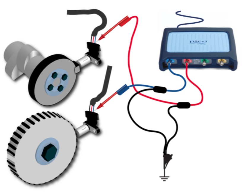
- Connect PicoScope Channel A to the crankshaft sensor;
- Connect PicoScope Channel B to the camshaft sensor;
- You can use a guided test to help you to set up the scope and to provide details on how to perform the test:
- Click on Guided Test in PicoScope 7 Software to open the guided tests window;
- Choose the grey System tests icon;
- Click on Camshaft position vs crankshaft position, and then again to display the buttons;
- Click on the Guide and settings file button;
- The guide will appear, and the PicoScope will be set up correctly with a sample waveform for you to examine.
- Start the scope to see live data;
- Start the engine and run at idle;
- With your waveform on screen, stop the scope;
- Use the Waveform Buffer, Zoom and Measurement tools to examine your waveform.
Cam Crank Correlation Demonstration
Phil is here to show us connections and software tips for cam and crank synchronisation with PicoScope.
Finding a Misfire using Engine Acceleration
A reliable way to determine whether a misfire is occurring is to check whether the engine accelerates during the power stroke. We use the Guided Test example waveform to show you how to display crank acceleration.
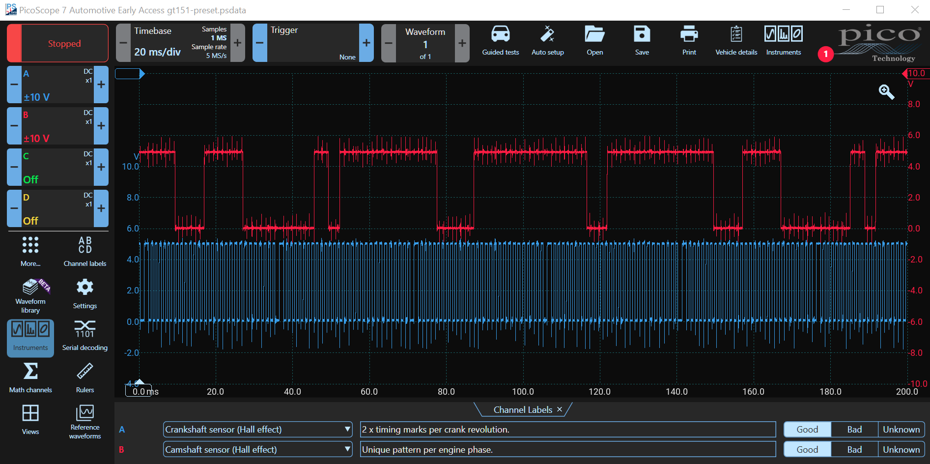
Notice the red '1' at the top right. That indicates that there is a message. Click on the '1' to see the message. Usually, the message informs you of available updates. You don't need a PicoScope to follow along. Download the software and load the guided test as described above.
Crankshaft Sensor Missing Teeth
The first step is to count the number of teeth on the crank sensor. Usually there is only one missing tooth index per revolution of the crankshaft (see the animation, above), but in the example waveform, there are two.
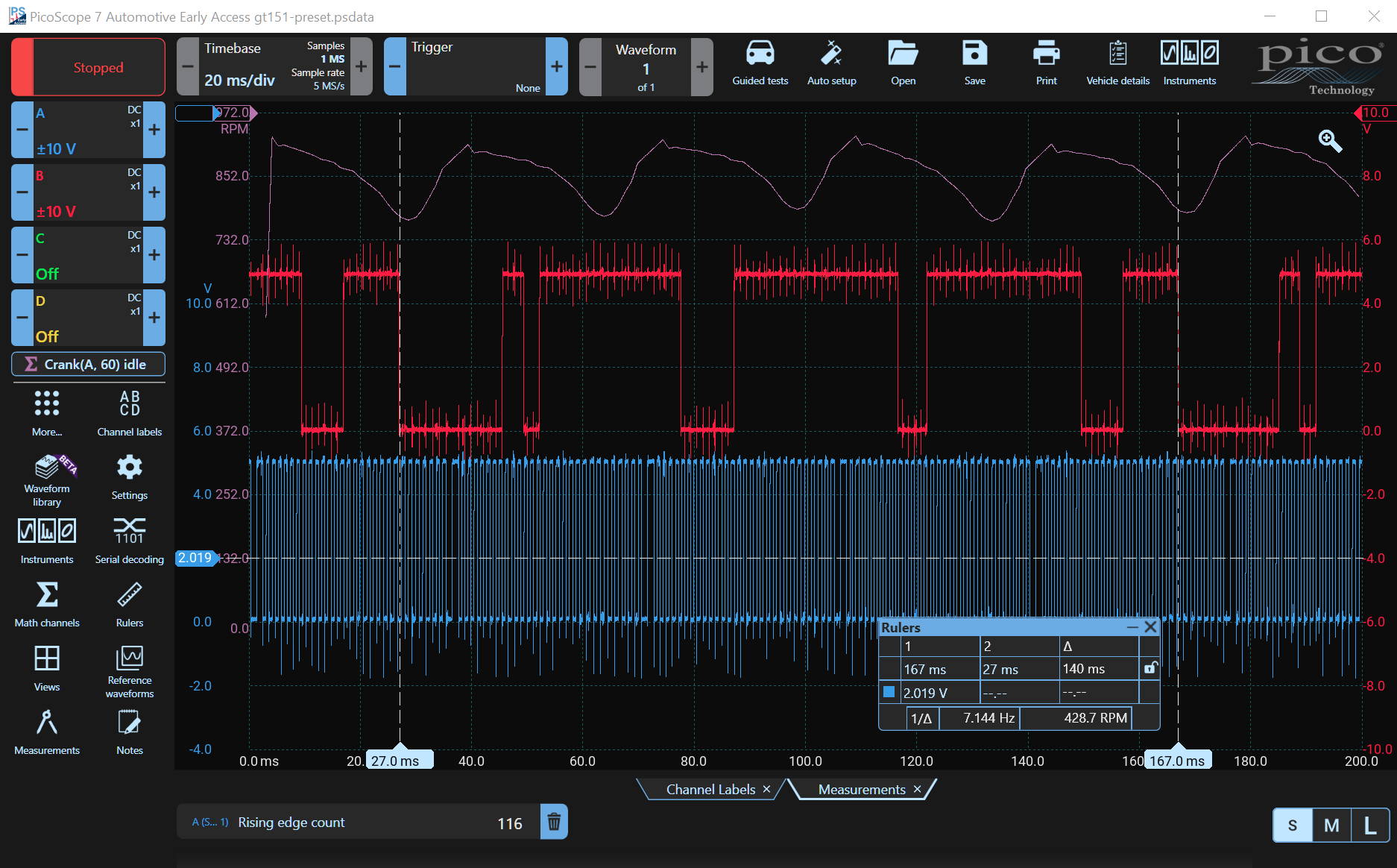
A camshaft rotates at half the speed of a crankshaft. Place a ruler on repeating transitions of the camshaft sensor (In the example, we placed the rulers at 27 ms and 167 ms). The time between the rulers delineates one camshaft rotation. PicoScope's ruler box shows that the cam shaft is rotating at 428.7 RPM. As the crankshaft rotates at twice the speed of the camshaft, it must be rotating at 857.4 RPM. Notice that there are four missing teeth between the sensors, not the normal two.
Count the Crankshaft Sensor Teeth using the Rulers
You can count the pulses manually, but it is much easier to allow PicoScope to count them for you.
- Click the Measurements Button. If it is not in your preferred menu, click More... to find it;
- Ensure that Channel A is selected (Crankshaft Sensor);
- Choose Rising edge count (do not select Edge count or the result will be doubled);
- The result should be 166, which is the number of edges across the entire screen;
- Click on the rising-edge count at the bottom of the screen;
- Choose Between Rulers and the count will decrease to 116.
Remember that there are four missing teeth, so the actual count is 120 per camshaft revolution. The crankshaft rotates at double the speed of the camshaft, so there are only 60 teeth per crankshaft revolution. Also note that in most cases, there is only one missing tooth per crankshaft revolution, so your waveform may be different to the example waveform.
Using a Maths Channel to display engine speed
The example waveform appears to have been generated by a hall sensor, and therefore all the pulses are the same amplitude, i.e. 5 V. If an inductive sensor was used, you would be able to see a slight amplitude increase as the crankshaft accelerates. This can be seen in the test animation above. A more reliable method is to use the tooth frequency. The maths channel has an invaluable function called "crank" that measures the crankshaft frequency and shows the crankshaft RPM speed. The general syntax is Crank (Channel Letter, Number of Teeth, including the missing teeth).
- Click the Math channels Button. If it is not in your preferred menu, click More... to find it;
- If it exists, select Crank(A, 60) idle from the list or click the + to add it and enter the formula: Crank(A, 60);
- Double-click the formula to modify it, and you can also change the waveform colour — we made it light purple;
- A new waveform appears showing the RPM;
- Notice the acceleration and deceleration of the waveform for each power stroke.
Camshaft Sensor and Crankshaft Sensor Waveform Analysis
The first (left) margin is close to the top-dead-centre of one of the cylinders. A cylinder can be identified by a number of means such as by adding an ignition waveform (e.g. by using a COP probe) or by adding an injector voltage or current waveform. Then you can use the firing order to determine the sequence.
The crankshaft has slowed because of the compression stroke. The power stroke begins, resulting in a sharp increase in engine speed.
This is a four-stroke, 4-cylinder engine therefore, there are two power strokes per crankshaft revolution and four power strokes per camshaft revolution, one for each of the four cylinders.
Look for regularity. Any missing peaks show a misfire.
Engine Timing
The relationship between the camshaft and crankshaft is vitally important as even a slight mismatch will affect the ECU's attempts to correctly control the engine. Of course, a gross mismatch can have catastrophic consequences.
One of the most useful features of PicoScope is the waveform library. There are thousands of waveforms available sorted by make and model. If you have an Automotive PicoScope (required to access the library), you can download both good and bad waveforms and compare them to your waveform to verify that your waveform is correct. This is invaluable for Cam Crank Correlation but is equally applicable to many other tests and waveforms. There are notes included that can help you diagnose problems more easily. You can upload known-good and bad waveforms from your vehicles which can be shared with all PicoScope users around the world.
Accessories
- PICO-TA404 to PICO-TA407: PicoBNC+ Premium Test Leads 3 m
- PICO-TA125 to PICO-TA128: BNC Premium Test Leads 3 m
Test Clips and Back-pinning Probes
- PICO-TA007: Insulation Piercing Clip Set
- PICO-TA008: Back-pinning Probe Set
- PICO-TA161 to PICO-TA162: Flexible Back-pinning Probes