


Top-10 Test 6: ABS Sensor
Test 6: ABS Sensor
The purpose of this test is to evaluate the operation of an Anti-lock Braking System (ABS) Hall Effect Wheel Speed Sensor based on its output voltage and frequency.
ABS Sensor (Hall Effect) Test Setup
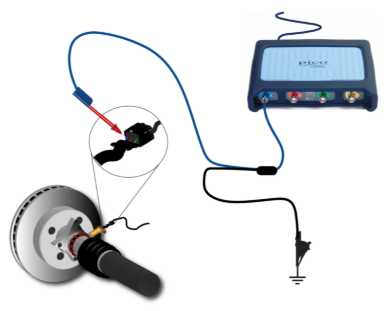
- Use the Manufacturer's data to identify the wheel speed sensor's output circuits;
- Connect your PicoScope Channel A to the sensor output;
- You can also connect other channels to the other ABS sensors if you wish;
- Use the Guided Test to set up the PicoScope and to get information
about the test:
- Click on Guided Tests to display the Guided Tests Window;
- Click the Red Sensors Icon;
- Choose Wheel Speed;
- Choose Wheel speed sensor (Hall effect);
- Click Guide and Settings File;
- The PicoScope will be setup for the test and a sample waveform will be displayed.
- Turn the ignition on but do not start the engine;
- Start the PicoScope to see live data;
- With the suspect wheel raised, turn it by hand. This will be enough to produce output from a good sensor;
- With your waveform on the screen, stop the scope;
- Use the Waveform Buffer, Zoom and Measurement to examine your waveform;
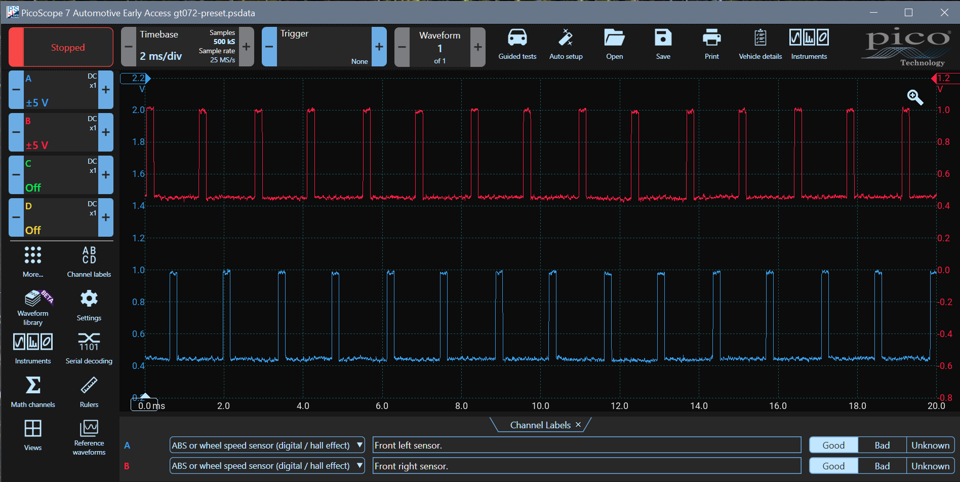
Inspect the waveform for uniformity across one complete revolution of the road wheel. The wheel speed signal should remain stable and uniform throughout each revolution of the wheel at a fixed speed. PicoScope will reveal anomalies such as poor signal formation, reduced amplitude and sequential changes to each pulse that could reveal ABS pick-up damage.
Waveform Notes
In this example, Channel A is connected to the left front wheel and Channel B is connected to the right front wheel.
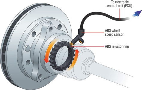
The hall effect device produces a pulse whenever a reluctor tooth passes the sensor. The voltage level might vary from manufacturer to manufacturer, but the frequency of the pulses is proportional to the wheel speed.
| ABS to Road Speed Calculator | ||
|---|---|---|
| Tyre Code: | / R | |
| Reluctor Teeth | ||
| Maths Formula (km/h) | 0.14733*freq(A) | |
| Maths Formula (miles/h) | 0.09155*freq(A) | |
Calculating Road Speed (Maths Channel)
One of the most useful but least understood features of PicoScope is the Maths Channel. This feature allows you to enter a formula, and the PicoScope will create a new waveform based on that result.
As a demonstration, we have included a tool that creates a formula that calculates road speed in km/h or in miles/hour using an ABS sensor as an input. The vehicle's ECU performs a similar calculation to control the speedometer.
Enter the tyre code and the number of teeth on the ABS sensor sprocket and then enter the formula into a maths channel on the oscilloscope. The PicoScope will display a road speed trace.
The A in the formula is the PicoScope input channel being used. You can change it if you are using a different channel.