


Top-10 Test 1: Relative Compression
Test 1: Relative Compression
The purpose of the Relative Compression test is to examine and compare engine cylinder condition by observing the electrical current being drawn by the starter motor during engine cranking.
During each compression stroke, the starter motor experiences resistance or a greater load, which means that it has to draw more current. Each current peak is therefore an indication of how good the compression is, across all cylinders.
How to perform the Relative Compression Test
- You need to prevent the vehicle from starting. One way to do this is to disable the vehicle's fuel injection
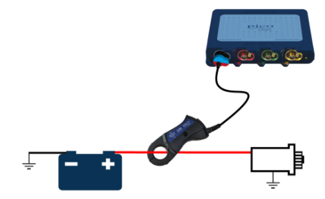
- Connect the high-amp (2 kA) clamp to PicoScope Channel A;
- If you are using a BNC clamp, select the highest range and zero the clamp. If you are using the PicoBNC+ clamp (PICO-TA388), the clamp's range is set up in PicoScope 7 and the clamp is zeroed automatically;
- Connect the clamp around the positive or negative battery lead;
- You can use the Guided Test to provide information and to set up the PicoScope for you:
- Click on the Guided Tests button at the top of the PicoScope 7 screen to open Guided Tests;
- Click the blue Charging and Starting Button;
- Choose Starting;
- Choose Relative Compression (gasoline)
- Click Guide and Settings File
- The Scope will be set up for you, and a comprehensive guide will be displayed showing you how to conduct the test.
- Start the Scope;
- Crank the engine for about 5 seconds to capture your waveform;
- Use the waveform buffer and zoom to examine your waveform.
Video Commentary
In this Compression Test animation, an exhaust valve on Cylinder 1 is not sealing properly (valve-stem bent).
Connect: Use your 2 kA current clamp and connect it to Channel A of the PicoScope. If you have the new 4225A or 4425A scope, you can use the new PicoBNC+ PICO-TA388 Current Clamp. PicoBNC+ allows the scope to automatically identify the clamp and sets up the scope automatically, saving you time and reducing errors. Fit the clamp around either battery cable. Make sure that the orientation of the clamp is correct with respect to conventional current flow.
Prevent the engine from starting. There are a number of ways to do this, such as disabling all the injectors. In this example, the fuel pump fuse is removed, which prevents fuel from reaching the engine.
Run: Crank the engine.
Read: Notice the initial high-current peak as inertia is overcome. As the engine compresses, the starter motor has to work harder, and it consumes more current. In this example, every fourth current peak is missing, indicating a lack of compression in one cylinder. Stop cranking when you have sufficient data.
Connect: Connect a COP probe such as the new PICO-TA398 PicoBNC+ COP Probe to channel B. Again, PicoBNC+ will set up the scope automatically. Although it is not clear from the video, the sensing end of the COP probe should be placed on top of the COP coil to pick up the magnetic field in the coil.
Run: Crank again.
Read: Notice the ignition events displayed in Channel B. The ignition event corresponds to a compression peak near TDC of the cylinder being probed. Use the firing order to identify the bad cylinder. In this video, assuming the firing order is 1 3 4 2, the ignition pulse occurs at cylinder 1, and therefore the cylinder with low compression is cylinder 4.
Good waveform
The waveform below is 'known good', the one loaded from the guided test. It shows all cylinders exhibiting equal pressure peaks.
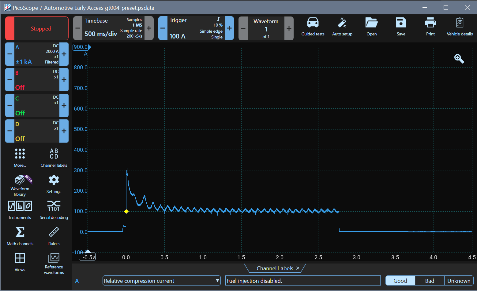
Waveform Analysis
A small increase in current is seen just before zero seconds. That is when the ignition is switched on. The large peak occurs because the starter motor has to overcome engine inertia. As the engine speeds up, the average current drops and the individual peaks showing cylinder compression appear. When cranking stops, the current reduces sharply. At about 3.7 seconds, the small drop in current shows when the ignition was switched off.
The current drawn by diesel engines is significantly higher due to the higher compression ratio.
Accessories
If you have a PicoBNC+ Oscilloscope such as the 4425A, then the PICO-TA388 is best. The economy PICO-TA019 (which is only suitable for small petrol engines) and the premium PICO-TA167 are for the 4823, 8-channel PicoScope and for the older BNC PicoScopes.
Use the new PICO-TA398 with the newer PicoBNC+ PicoScopes and the PICO-PP357 with the older BNC PicoScopes.
- PICO-TA388 2,000 A Current Clamp with PicoBNC+
- PICO-TA019 600A Current Clamp BNC (Petrol Engines Only)
- PICO-TA167 200 A / 2,000 A Current Clamp BNC
- PICO-TA398 COP Probe with PicoBNC+
- PICO-PP357 COP Probe set with BNC