CAN Bus Testing and Serial Decoding
CAN Bus Testing and Serial Decoding

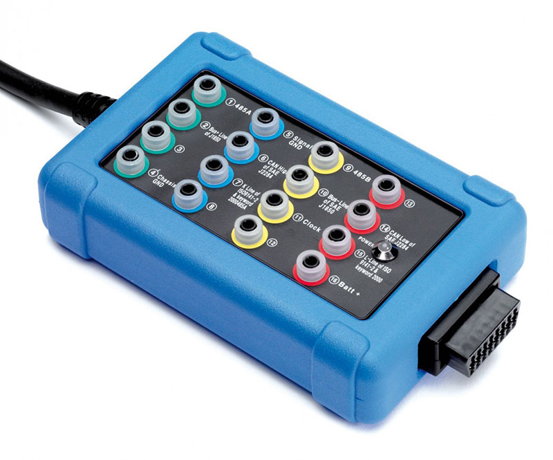
The CAN Bus Test Box connects to a vehicle᾿s OBD / DSL connector and helps you to diagnose electrical faults.
- Instantly check power and ground circuits
- Identify communication link protocols
- Connect an oscilloscope for signal capture and collection of signal waveform data
- Compatible with both 12 V and 24 V vehicles
Also, have a look at Test 9: CAN Bus — one of the Top Ten Tests. Our Demo Mode Course now includes a new CAN Module. Also, go to the Product page for more detailed information and pricing.
Communication Networks Series
Here is a list of available videos in the series. The first six are available at present, below. Video 7 is to follow:
- 1. Demystifying Network Terminology (Jargon Buster)
- 2. Network Measurements
- 3. LIN Bus (Local Interconnect Bus)
- 4. CAN Bus (Controller Area Network)
- 5. FlexRay
- 6. SENT (Single Edge Nibble Transmission)
- 7. 10Base-T1S (Automotive Ethernet)
Part 1: Terminology
In this video Andy and Steve look at the terms used when working with vehicle networks. The terminology can sound daunting and almost alien in automotive applications; however, we hope this video serves as a reference to cut through the jargon to help with self-study and vehicle diagnosis.
Running time: 40 min.
Part 2: Measuring Communication Networks
In this video, we are introduced the acronym C.A.N:
- Can messages be sent?
- Are messages being sent/acknowledged?
- Node
Here, Andy and Steve demonstrate several measurement techniques associated with the network diagnosis (focusing on CAN) with a few surprises along the way.
Running time: 1hr 10 min.
Part 3: LIN Bus
In this video, Andy and Steve discuss LIN bus Networks by combining theory with practical measurements to support a complete understanding of this widely adopted protocol. In addition, we follow the C.A.N diagnostic approach to locate a communication fault with a LIN bus pressure sensor. Look out for the LIN Bus bonus video to be released next month, where we convert serial data into human-readable values.
Running time: 53 min.
Part 4: CAN Bus
In this video Andy and Steve demonstrate how to use PicoScope hardware & software to tackle two CAN-faults. In addition, they generate several "typical" CAN-faults and discuss their impact on network communication.
Running time: 1 hr 10 min.
Part 5: Flexray
In this video, we step up a gear to analyse FlexRay, a high-speed (10 Mbps), fault-tolerant network used for safety-critical systems like ADAS and steer-by-wire. Because of its speed and sensitivity. Measuring FlexRay requires specific techniques to avoid creating faults on the vehicle.
Key Topics & Demonstrations:
- The good, the bad, and the ugly of Probing: We demonstrate why using a standard x1 test lead causes network intrusion and generates fault codes due to impedance issues, and why x10 probes are essential.
- Physical Layer Analysis: Understanding the differential voltages (Bus Plus and Bus Minus) and the specific idle and dominant states of the protocol.
- Automated Diagnostics: How to use Math Channels (A+B) combined with Mask Testing and Actions to automatically catch physical layer faults, such as a short to ground, while you are away from the screen.
- Differential Probes: A tip on using a differential probe to capture the full network packet using only one scope channel, saving resources for other signals.
Running time: 51 min.
Part 6: Sent
In Video 6 of our series, we dive deep into the SENT (Single Edge Nibble Transmission) protocol to understand how modern vehicles are moving from analogue to high-resolution digital sensors. Learn how to diagnose this unidirectional, point-to-point protocol using an oscilloscope and decode the data streams that control critical systems like fuel rail pressure and mass airflow.
Key Diagnostic Concepts Covered:
- What is SENT? Understand the shift to digital data where a single sensor can report multiple parameters (e.g., pressure and temperature) on one wire.
- The Calibration Pulse: Learn why the Calibration Pulse is critical for decoding. We show you how to measure this pulse (typically 168 µs) and divide it by 56 to find the fundamental Tick Time (usually 3 µs).
- Packet Structure: A breakdown of the signal, including Status, Data Nibbles, and the Checksum, all defined by the time interval between falling edges.
- Fast vs. Slow Channels: Discover how SENT transmits critical data (like pressure) via the "Fast" channel while simultaneously sending error codes and sensor info via the "Slow" channel over multiple packets.
- Practical Testing: How to use the decoder to see decimal values change in real-time as you stimulate the sensor, verifying operation even without converting to human-readable units immediately.
Whether you are dealing with a fault code or verifying a new sensor, this video provides the essential theory and practical tips needed to master SENT diagnostics.
Running time: 59 min.
Video Presentation
Barney and Steve will describe the PicoScope features and techniques that you use to help you diagnose faults in CAN bus systems. Firstly, they will show you how to check the network physically and find common circuit faults. Then they will explore PicoScope's serial data decoding feature and how it can be used to examine CAN communications.
Running time: 1 hr 14 min.
CAN Bus Q&A
Barney, Steve, and Ben will be answering questions asked during and after the "Pico Practical: CAN Bus Diagnostics and Serial Data Decoding" presentation.
Running time: 55 min.


