


A new Demo Mode Course has been created.
PicoScope Channel Setup - Channel A Injector Voltage
Vertical Channel Setup - Channel A
Understand channel setup. This section is quite lengthy so that you can understand the features, but in practice, you will find that channel setup can be done very quickly.
If you are using the new PicoScope 4425A or 4225A, with PicoBNC+, the PicoScope 7 Software will set up the channel automatically for you when you plug in a PicoBNC+ Accessory.
Demo Device Channel Summary
The demo device simulates a four-channel PicoScope connected to a vehicle as follows:
| Channel | Description | Vertical | Probe | Coupling |
|---|---|---|---|---|
| Channel A | Injector Voltage | ±100V | Test Lead | DC |
| Channel B | Injector Current | ±2A | 20/60A Current Clamp / PicoBNC+ Current Clamp 60A | DC |
| Channel C | Primary Ignition | ±400V | Attenuator 10:1 / 10:1 Probe | DC |
| Channel D | Crank Sensor | ±5V | Test Lead | DC |
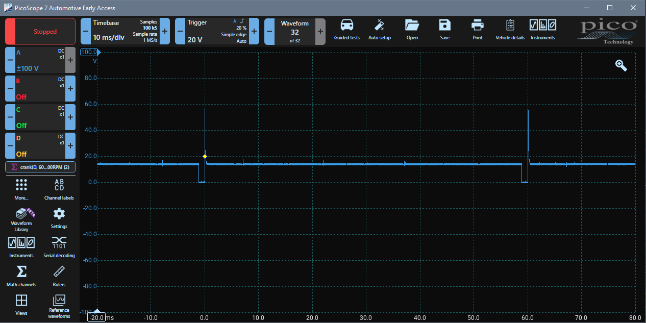
We will start with Channel A. Switch off channels B, C and D by clicking on each channel control and clicking Off. You should be left with the Channel A waveform.
Channel Setup: Channel A
The channel setup of Channel A should be: ±100V; with a 1x Probe; DC Coupled. Click on the Channel A Control. The Channel Menu Panel should appear. The first tab (Vertical) is used most, so it is selected by default. Make sure that ±100V is selected. The coupling mode should be DC and invert should be off.
Probe Selection Tab
Check that the correct probe is selected, so click on the Probes tab at the top of the Probe Menu Panel. The 'X1 No scaling probe' should be selected.
DSP Tab
The Digital Signal Processing or DSP Tag is used for filtering and resolution enhancement. We don't need these features here so ensure that the Low pass filter is turned off and resolution enhance is set to 12 bits (no enhancement, the PicoScope is 12 bits). Filtering and resolution enhancement are useful tools which we will introduce later, however, using them results in a reduction in frequency response.
Display Tab
The Display Tab is for scaling the waveform on the display. Keep the Scale at x1 (No Scaling) and the offset at 0% to start.
Moving the Waveform Vertically - Offset
When performing channel setup, you need to arrange the waveforms so that you can see them clearly
You can move them so that they don't overlap. Click on the blue scale on the left of the waveform (the Channel A Voltage Scale), and you can drag the waveform up and down. As you move it, zero is represented by a horizontal line, so you can align it with a grid line. Move the zero up two divisions, and the Channel A waveform will be near the top of the display.
You can also set the offset manually. Click on the Channel A control and then on Display, and you will see that the Offset has changed to 20%. Which means that you moved it up by 20% of the full display height. Change the offset back to 0% for now, which will move the waveform 0 V back to the middle of the display.