PicoScope Channel A Setup Injector Voltage
Vertical Channel Setup - Channel A
This section is quite lengthy so that you can understand the features, but in practice, you will find that channel setup is done very quickly.
Remember that if you are using the new PicoScope 4425A or 4225A, with PicoBNC+, the PicoScope 7 Software will set up the channel automatically for you when you plug in a PicoBNC+ Accessory. You won't need to select the probe, but you may need to modify the standard setup to suit your application.
If you are using the 4823 or an older PicoScope or you are using a BNC accessory, you will need to select the probe yourself and set up the channel. Remember to always set up the probe first.
Demo Device Channel Summary
The demo device simulates a four-channel PicoScope connected to a vehicle as follows:
| Channel | Description | Vertical | Probe | Coupling |
|---|---|---|---|---|
| Channel A | Injector Voltage | ±100V | Test Lead | DC |
| Channel B | Injector Current | ±2A | 20/60A Current Clamp / PicoBNC+ Current Clamp 60A | DC |
| Channel C | Ignition | ±1V | COP Probe | DC |
| Channel D | Crank Sensor | ±20V | Test Lead | DC |
There are also two new CAN signals: CAN-H and CAN-L which will be used later in the course.
Switch Off Unneeded Channels
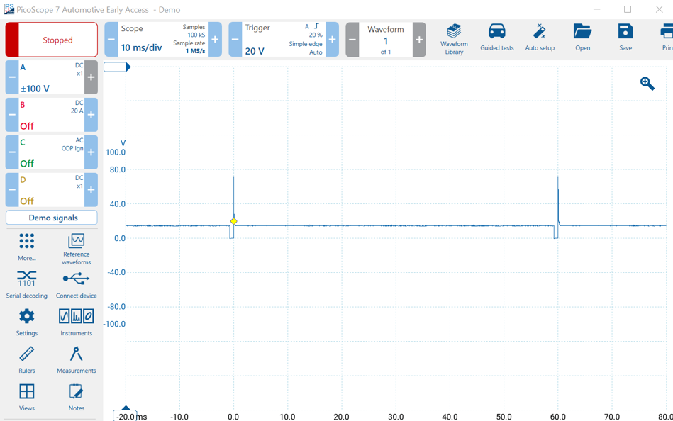
We will start with Channel A. Switch off channels B, C and D by clicking on each channel control and clicking Off. You should be left with the Channel A waveform. This is a good practice. Unneeded channels consume resources when enabled and also slow down the scope.
Channel Setup: Channel A
Channel A monitors Injector Voltage. Although injectors usually (but not always) run on battery voltage, the coils produce large back EMF spikes at switch off. That is why 100 V of head-room is needed. You can clearly see the large 70 V spikes in the image above.
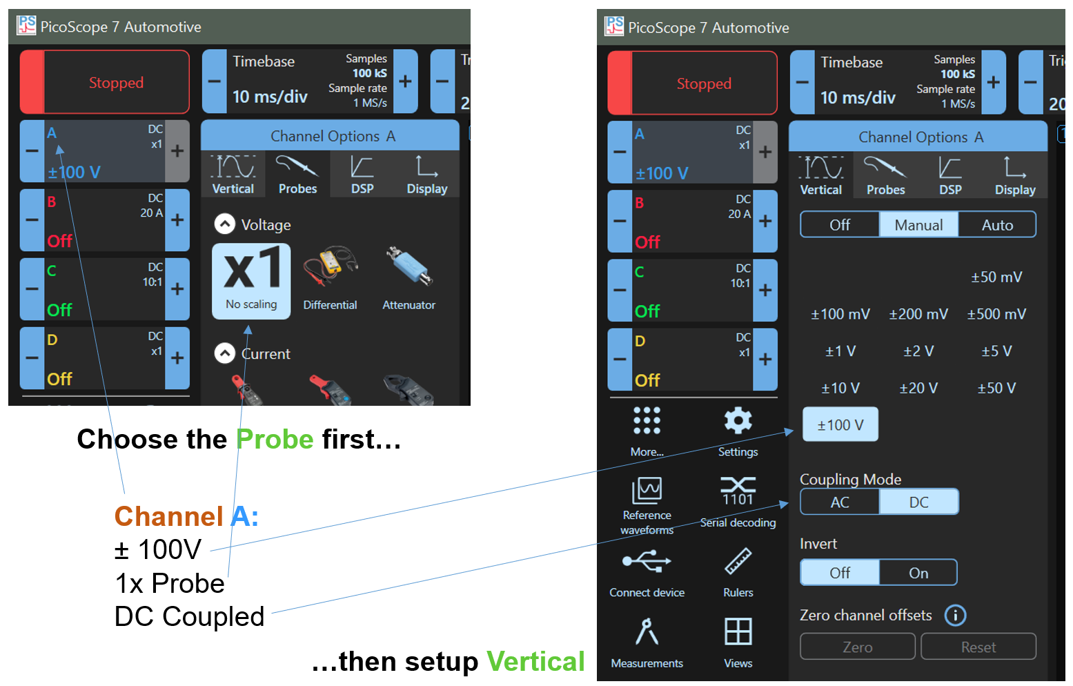
Probe Selection Tab
Click on the Channel A Control, also known as a 'lozenge'.
Check that the correct probe is selected, so click on the Probes tab at the top of the Probe Menu Panel. The 'X1 No scaling probe' should be selected.
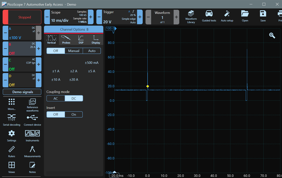
Vertical
The channel setup of Channel A should be: ±100V; with a 1x Probe; DC Coupled. The Channel Menu Panel should appear. Select the first tab (Vertical). Make sure that ±100V is selected. The coupling mode should be DC and invert should be off.
DSP Tab
The Digital Signal Processing or DSP Tag is used for filtering and resolution enhancement. We don't need these features here so ensure that the Low pass filter is turned off and resolution enhance is set to 12 bits (no enhancement, the PicoScope is 12 bits). Filtering and resolution enhancement are useful tools which we will introduce later, however, using them results in a reduction in frequency response.
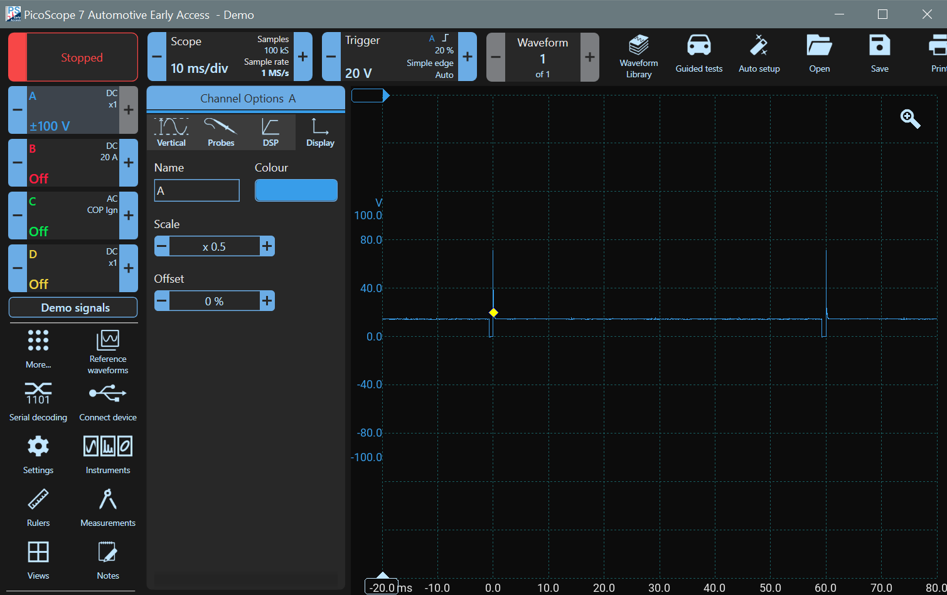
Display Tab
The Display Tab is for scaling the waveform on the display. Keep the Scale at x1 (No Scaling) and the offset at 0% to start.
Scaling and Offset
When performing channel setup, you need to arrange the waveforms so that you can see them clearly
Scaling
Scaling changes the size of the waveform on the display without altering how it is stored or captured. We can reduce its size so that we can fit more waveforms on the display.
Scaling by x0.5 means that the waveform will be half (0.5x) of its size. Notice how the scale on the side of the waveform changes as you scale.
Offset
You can move your waveforms so that they don't overlap. Click on the blue scale on the left of the waveform (the Channel A Voltage Scale), and you can drag the waveform up and down. As you move it, zero is represented by a horizontal line, so you can align it with a grid line. Move the zero up two divisions, and the Channel A waveform will be near the top of the display.

You can also set the offset manually. Click on the Channel A control and then on Display, and you will see that the Offset has changed to 20%. Which means that you moved it up by 20% of the full display height. Change the offset back to 0% for now, which will move the waveform 0 V back to the middle of the display.