


PicoScope Ignition Analysis using a COP Probe<
Ignition Waveform — Channel C
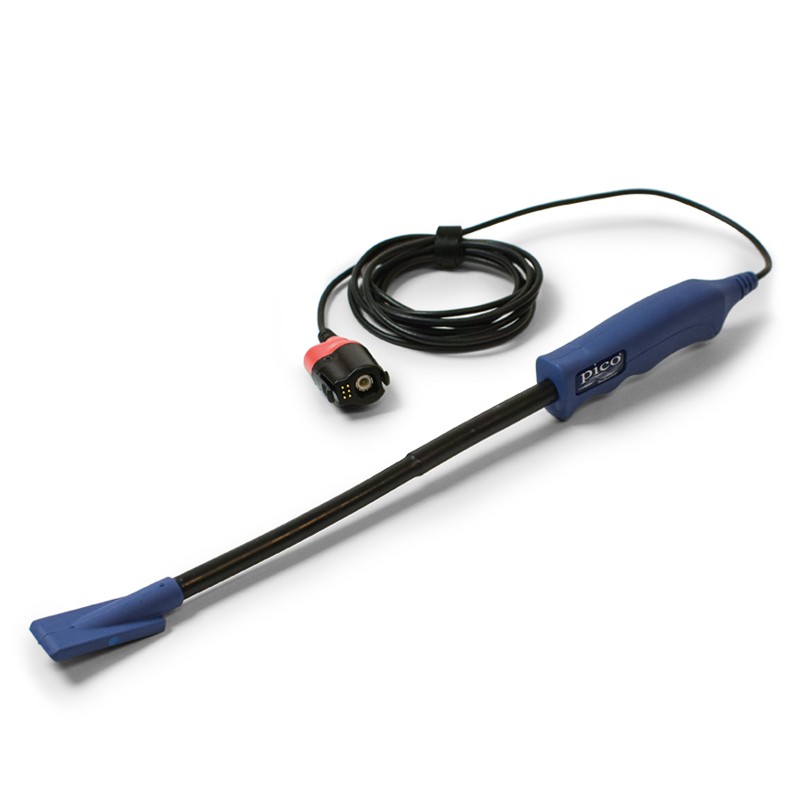
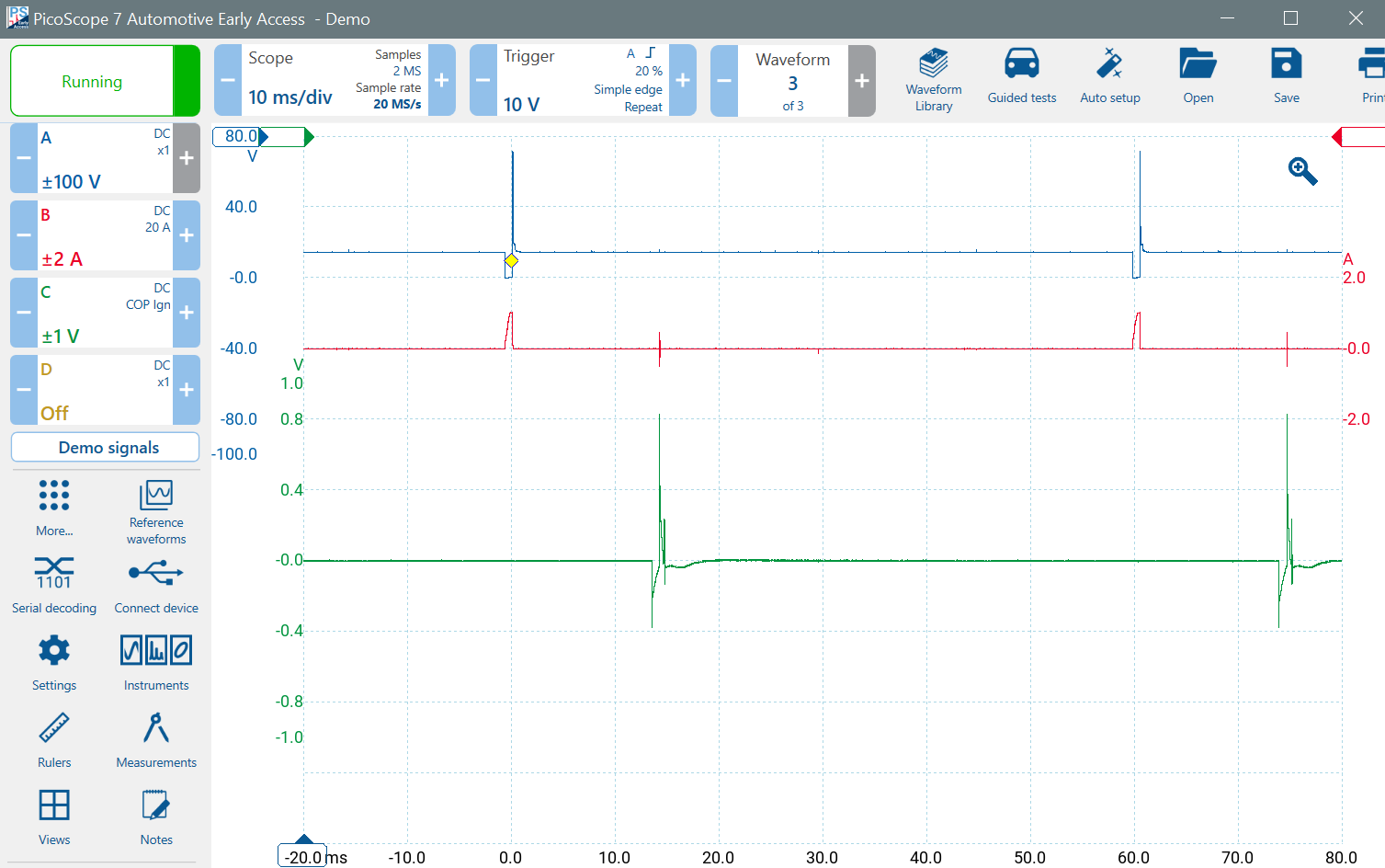
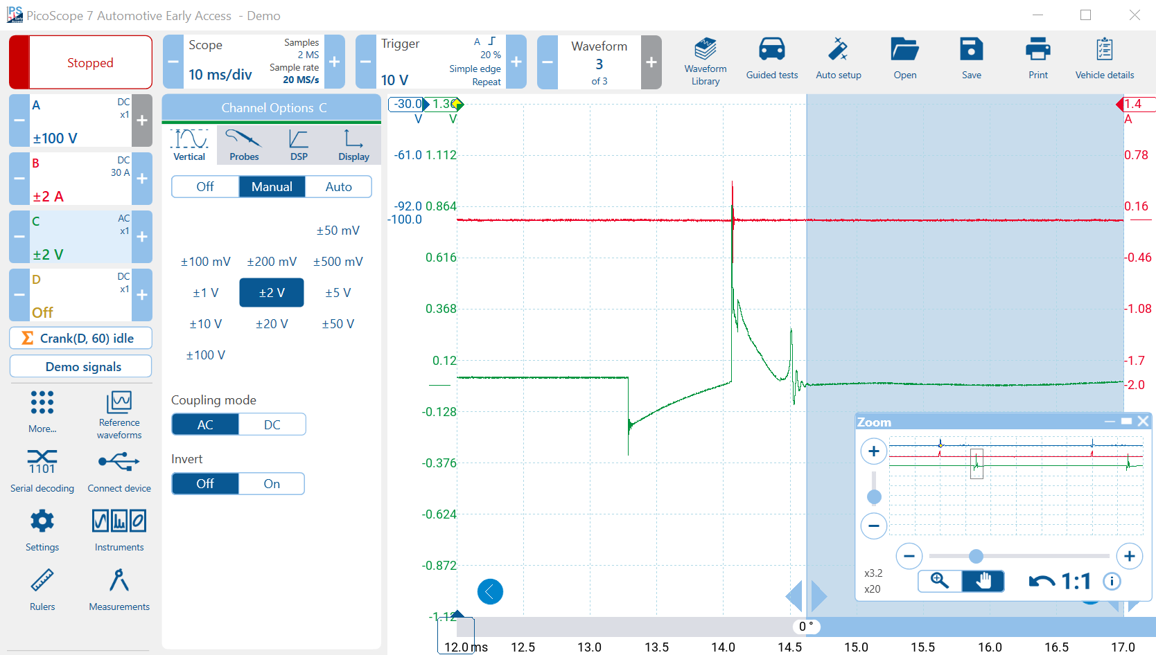
Channel C is looking at ignition using a COP Probe. Click on the Channel C control and set it up as follows:
The probe should have been selected automatically as it is PicoBNC+.
- Probes Tab
- Select the PICO-TA398 COP Probe
- Vertical Tab
- Select ±1 V
- Invert Off
- DSP Tab
- Low-Pass Filter Off
- Resolution-Enhance 12 bits
- Display Tab
- Scale x0.5
- Offset -20%
Understanding the COP Probe Output
You might have noticed that the voltage chosen above (±1 V) was rather low for an ignition waveform. The spark plug ionisation voltage spike can reach 10 kV, and the coil primary voltage spike is about 400 V, and the battery voltage is about 14 V when the engine is running. The COP probe is not connected, it only sees the magnetic field in the ignition (COP) coil. Therefore, the absolute voltage is really meaningless. The chosen voltage is the output voltage of the COP probe when it converts the magnetic field intensity to voltage.
You should move the COP probe around, close to the coil on plug's coil to get the best results. Sometimes the COP probe output exceeds 1 V. Merely adjust the channel voltage to correct any over-range.
The COP Probe is not electrically connected to the vehicle. It is coupled to the magnetic field. Therefore, the coupling is AC and you will not see DC voltages because only changes in the magnetic field are detected. Any constant (DC) voltages will collapse towards zero. Remember that the ignition timing is correct when using the COP Probe, but you need to be connected to measure any DC voltage levels.
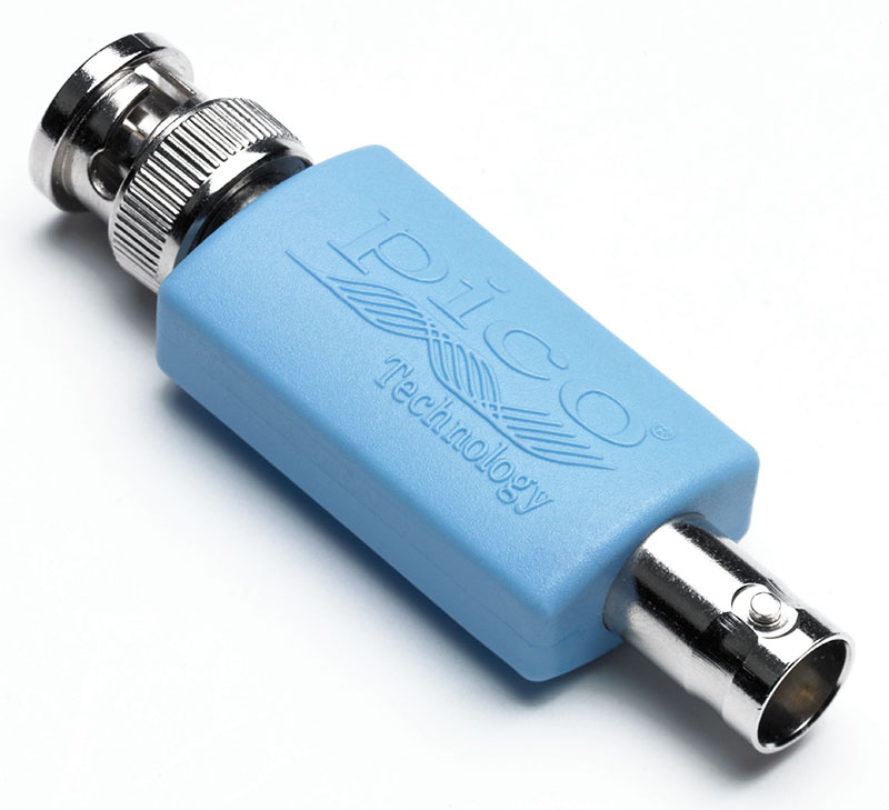
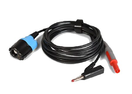
If you do want to look at the primary ignition voltage waveform directly, ALWAYS use a 10:1 probe or an attenuator with a BNC test lead. If you don't, your PicoScope could be damaged.
Part 2 of the Introduction to PicoScope Video
Welcome back to Part 2 of our PicoScope 7 Basics series! In this tutorial, we dive deeper into the core analysis tools and software settings that will speed up your diagnostic workflow. Whether you are a beginner or just looking to refresh your skills, mastering these features is essential for accurate waveform analysis.
Key Topics Covered in This Guide:
Customising Your Setup: Learn how to switch between Light and Dark mode, change system languages instantly, and adjust line thickness for better visibility. We also cover optimizing the panel layout for touchscreen users.
Advanced Zoom Controls: Discover how to effectively navigate large captures using the marquee zoom, mouse wheel, pinch-and-zoom gestures, and the panning tool.
Mastering Rulers: A deep dive into using Channel (vertical) and Time (horizontal) rulers to measure voltage and time differences. We also demonstrate Phase Rulers, showing you how to partition a waveform into 720 degrees to perfectly map out a 4-stroke engine cycle.
Automated Measurements: Stop guessing and let the software do the work. Learn the critical difference between "Maximum" (peak sample) and "Top" (filtered average) measurements, and how to apply these measurements to specific sections of your waveform using time rulers.
Reference Waveforms: See how to create an exact carbon copy of a "known good" signal.
We show you how to overlay this reference onto your live capture, making comparative diagnostics on the vehicle incredibly fast and easy.
Make sure to master these fundamental tools so you can analyze your electrical and engine signals with confidence!
Running Time 24 min 58 sec
Examining the 4-stroke Cycle with Rulers
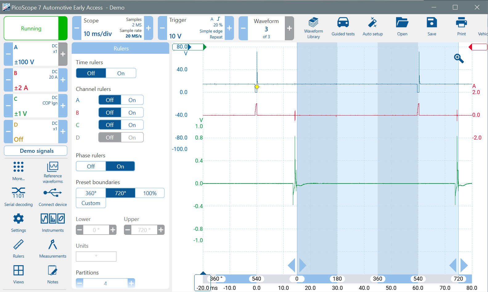
Using Phase-Rulers, we can examine the 4-stroke cycle and split it up into individual strokes. Click on Rulers in the main menu area or click More... to find it.
Turn on the Phase Rulers and use 720° as a Preset Boundary with four Partitions for the four strokes. Align the left ruler just after the first ignition spike and the right ruler just after the third ignition spike.
Keep in mind that the rulers probably do not align with Top Dead Centre (TDC) accurately. We are just guessing as to how advanced the ignition is and assuming that it is a few degrees before TDC. Also consider that the engine rotational speed is not uniform. The engine slows during compression and accelerates during combustion.
Examining and Interpreting Engine Timing
Oscilloscope diagnostics is all about analysing the waveform carefully and using your reason to try to picture what is happening in the engine. From the above waveforms:
- About six degrees after the spark, the piston will be at 0° or Top Dead Centre (TDC). This is the approximate position of the left ruler. At that point, the combustion stroke begins.
- At 180° the engine will be at Bottom Dead Centre (BDC). The exhaust stroke begins.
- At 360° the engine will again be at TDC. The inlet stroke begins.
- At 540° the engine will again be at BDC. The compression stroke begins.
- The injector opens just after 540°.
Is it Port-Injection?
If this is a port injection system, the injector would usually open earlier, around or before 450° to inject fuel into the airflow during the inlet cycle. Although the inlet valve is usually still open during the first part of the compression cycle, the airflow is very reduced because the piston has already reached BDC.
Is it In-cylinder Injection?
If this is an in-cylinder (direct) injection system, then the injection would probably occur after the inlet valve is closed, probably around 630°. Injection whilst the inlet valve is still open may allow fuel to exit the cylinder into the inlet manifold.
Is the Engine Timing correct?
Therefore, it appears that the injection in this example might be occurring in the wrong place. What could be wrong? We will revisit and examine these observations in greater detail when we look at the crankshaft sensor signal, next.
Using the Time Rulers
Drag two (white) Time Rulers across from the left of the timebase scale at the bottom. Align them with the falling edge of the injector current spikes on Channel B. Use Zoom to place the rulers accurately. Tip: As the left ruler is at the trigger point, you can also enter 0 in the ruler box to align it with the trigger.
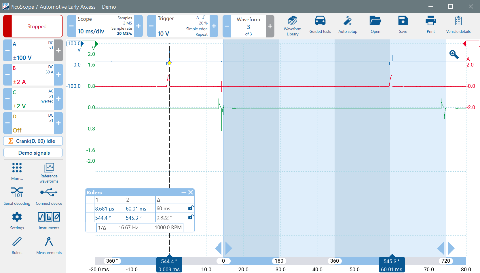
PicoScope reveals quite a lot of information in the ruler box. Firstly, the difference in time between the two rulers (60 ms). Then, the elapsed rotational angle between the phase rulers and the time rulers and the difference between the time rulers in degrees of rotation. Finally, the RPM of the engine is shown.
Be careful when using the Frequency or RPM Figure
You have set the two time rulers 720° apart — two revolutions. The frequency measurement is automatically derived from the actual time difference between where you place the time rulers. You must position them correctly. Because you have placed the rulers to cover two revolutions, the actual engine RPM is 2,000 RPM, twice the displayed RPM (1,000 RPM).
To summarise: PicoScope calculates frequency = 1 / time between rulers. Frequency is measured in Hz, which is cycles per second. To convert to RPM (revs per minute), PicoScope just multiplies the frequency by 60.
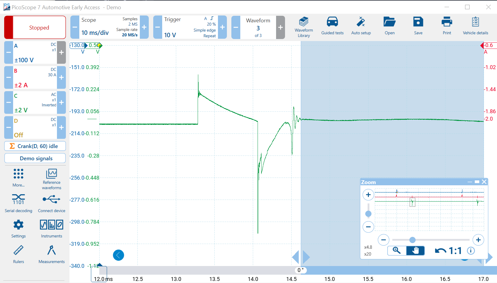
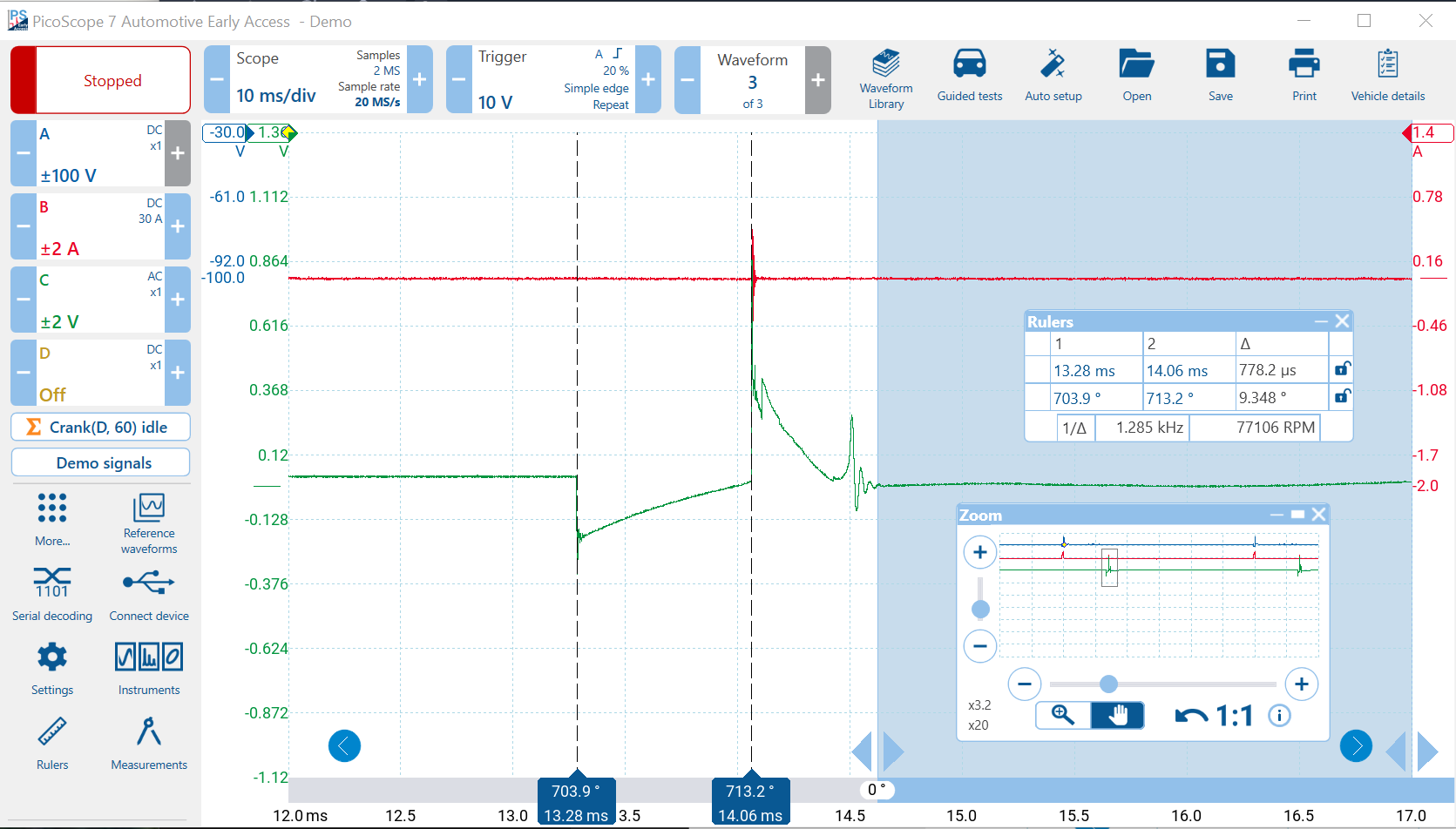
Examining the Ignition Event
Zoom into the first ignition event. Conventionally, the ignition is at battery voltage (14 V) and pulled down during the dwell time. The ionisation pulse is at +10 kV. We have a problem; the ignition is upside down. This can easily happen when you use a COP Probe, the orientation is dependent on the polarity of the magnetic field where you are sensing it.
Invert the Waveform
To correct this, we just need to invert the channel. Click on the Channel C control and set the Invert Channel checkbox to Off if it is On, or vice versa to invert it.
Measuring the Dwell Time
Use a pair of time rulers to measure the dwell time. Place the first ruler where the voltage goes low and the second at the ignition spike. (Use Zoom for accuracy). During this time, using old Kettering terminology, the points are closed and current is building up in the coil. The difference between the two rulers is approximately 778 μs.
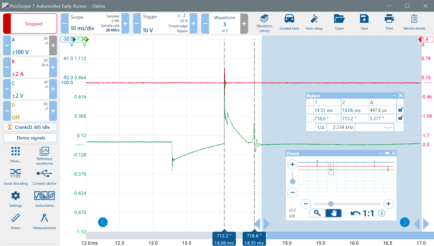
Measuring the Burn Time
Now we can measure the burn time. After the high-voltage spike that ionises the air between the spark plug electrodes, current starts to flow and power is dissipated. That heats up the ionised air (which has a small thermal mass) - white-hot - forming the spark. The duration of the current flow is called the burn time. Move the first time pointer to the little peak just before the voltage collapses. The burn time is about 448 μs. The oscillations at the end are expected. If they are absent, the ignition coil might be faulty.
Noise
Notice how the noise on the current waveform on Channel B aligns with the ionisation waveform on Channel C. This is because the noise is caused by the current flowing through the coil being picked up by the current clamp which is nearby. Noisy circuits such as ignition can interfere with nearby accessories such as current clamps. Notice that the noise picked up by the clamp is not consistent for all COP coils. Distance reduces the noise amplitude, so try to locate your test accessories away from sources of noise.
Burn Time Voltage Shape
The shape of the burn-time voltage can provide further information such as whether the mixture is rich, lean or turbulent, but that is beyond the scope of this course.
Close the Zoom and Rulers Boxes and switch off the Phase Rulers. Next we will examine the Crank Sensor on Channel D in a quest to find a misfire.