


A new Demo Mode Course has been created.
Ignition Waveform — Channel C
Ignition Waveform — Channel C
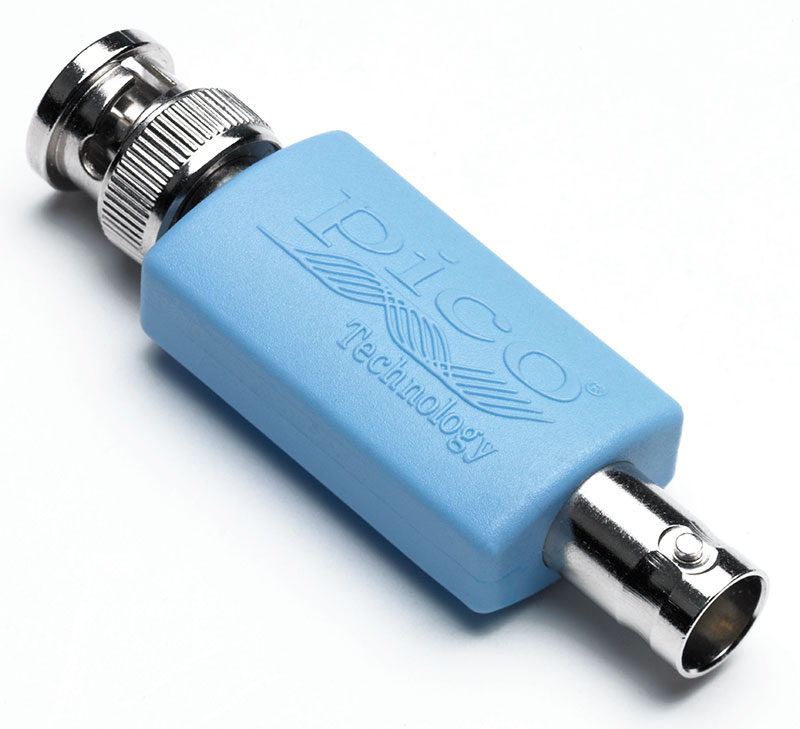
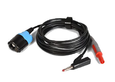
Channel C is looking at a primary ignition waveform using a 10:1 attenuator. A PicoScope can measure up to ±200V on its inputs. However, primary ignition can exceed that and can damage the scope, so always use an attenuator with the older BNC scopes or the PICO-TA499 PicoBNC+ 10:1 Scope Probe< with the new 4425A when testing primary ignition. Click on the Channel C control and set it up as follows:
- Vertical Tab
- Select ±400V
- Invert Off
- Probes Tab
- Select the PICO-TA197 Attenuator, then 10:1
- DSP Tab
- Low-Pass Filter Off
- Resolution-Enhance 12 bits
- Display Tab
- Scale x0.5
- Offset -40%
Notice that PicoScope tries to use a unit multiple that makes sense for the waveform being displayed. It might change the display to measure in kV rather than V to save horizontal space in the scale on the side.
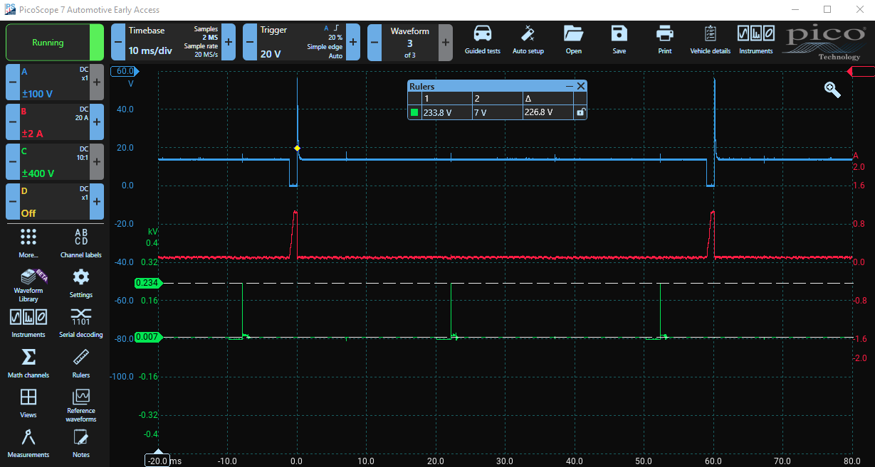
Using Rulers to measure voltage
On the left of the display, you will see a green arrow at the top. Click on it and a ruler will appear. Drag the ruler down to the top of the spike to see what the voltage is.
You can drag down another green ruler for Channel C. Align it with the flat area between ignition events. You may find it difficult to be accurate, so zoom into a box around the first ignition event and then adjust the rulers. Zoom in even further for more detail if necessary.
You can also set the ruler levels manually. Try clicking on the ruler box under 2 and enter 7 for the green ruler. That will set the ruler's level to 7 V. Now you can see the voltage at the top of the spike, the quiescent voltage between ignition events and the difference between them.
Close the zoom box and the ruler levels will be maintained.
Wasted Spark
Examining the ignition waveform, the vehicle being tested appears to be using a Wasted Spark System where cylinders are fired in pairs. One cylinder undergoes combustion when the spark is fired whilst the other is busy closing its exhaust valve just before opening its inlet valve, and that spark has no effect. This is a cost-saving measure to reduce the number of ignition components required.
This engine appears to have 4-cylinders, so there are two wasted spark systems, the ignition events from only one system are shown. The location of the other two ignition events can be inferred from the little spikes on the Channel A signal and the little spikes on the Channel C signal between ignition events. Notice how the ignition events align with the interference on Channel A.
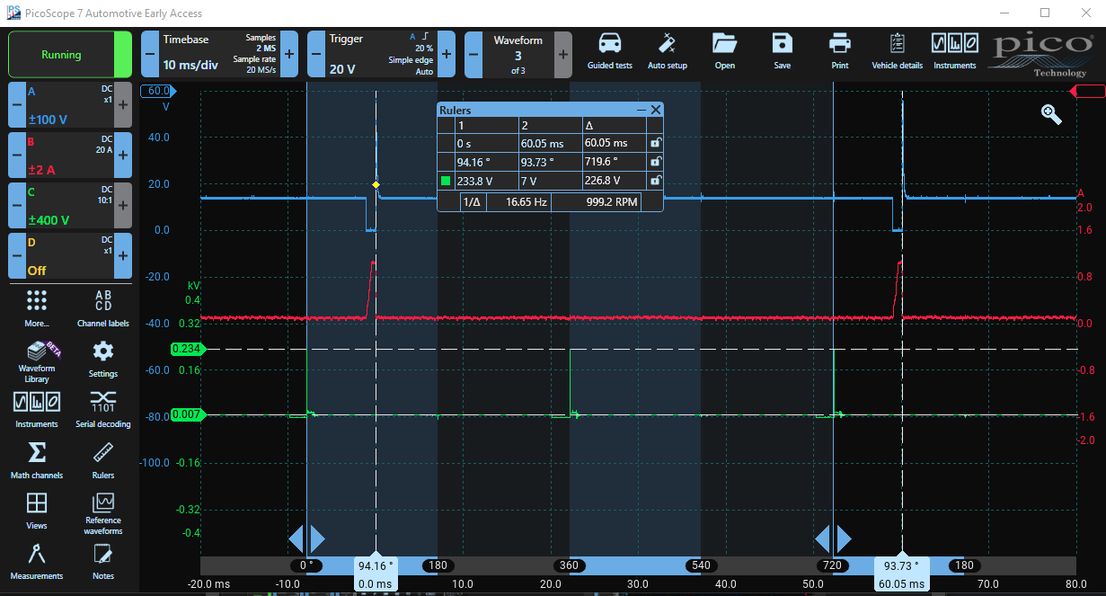
Examining the 4-stroke Cycle with Rulers
Using Phase-Rulers, we can examine the 4-stroke cycle and split it up into individual strokes. Click on Rulers in the Main manu area or click More... to find it.
Turn on the Phase Rulers and use 720° as a Preset Boundary with four Partitions for the four strokes. Align the left ruler with the first ignition spike and the right ruler with the third ignition spike. Use Zoom to align accurately.
Notice that the second ignition event aligns with 360°, and the two other ignition events (not displayed but revealed by the little spikes) occur at 180° and 540°.
Remember that these rulers probably do not show Top Dead Centre (TDC) accurately because ignition usually occurs a few degrees before TDC.
Using the Time Rulers
Drag two (white) Time Rulers across from the left of the timebase scale at the bottom. Align them with the voltage spikes on Channel A. Again, use Zoom for accuracy. As the left ruler is at the trigger point, you can enter 0 in the ruler box to align it with the trigger.
PicoScope reveals quite a lot of information in the ruler box. Firstly, the difference in time between the two rulers (60.05 ms). Then, the elapsed rotational angle between the phase rulers and the time rulers and the difference between the time rulers in degrees of rotation. Finally, the RPM of the engine is shown.
Be careful when using the Frequency or RPM Figure
You have set the two time rulers 720° apart — two revolutions. The frequency measurement is automatically derived from the actual time difference between where you place the time rulers. You must position them correctly and remember that The phase rulers play no part in calculating RPM. Because you have placed the rulers to cover two revolutions, the RPM in this example is twice the displayed RPM — i.e. 2,000 RPM.
To summarise: PicoScope calculates frequency = 1 / time between rulers. Frequency is measured in Hz, which is cycles per second. To convert to RPM (revs per minute), PicoScope just multiplies the frequency by 60.
Which injector supplies which cylinder?
Assuming that this engine uses port injection, fuel is likely to be introduced during the intake stroke. Thus, it seems likely that the injector shown supplies fuel to the cylinder that fires at 360°. That cylinder's:
- intake stroke starts shortly after 0° on the display;
- its compression stroke starts just after 180°;
- its power stroke after the ignition at 360°; and
- its exhaust stroke starts shortly after 540°.
The other two displayed ignition events at 0° and 720° are 'wasted' in this cylinder but are proper ignition events in the corresponding cylinder, 360° out of phase.
Close the Rulers Box and switch off the phase rulers using the Rulers-Menu.
Examining the Ignition Event
Zoom into the first ignition event. Use a pair of time rulers to calculate the dwell time. Place the first ruler where the voltage goes low and the second at the ignition spike. During this time, using old Kettering terminology, the points are closed and current is building up in the coil. The difference between the two rulers is approximately 2 ms.
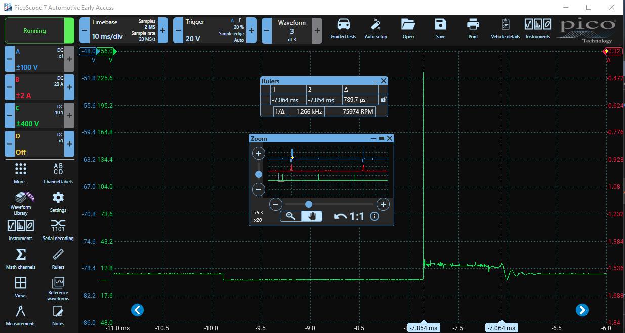
Now we can calculate the burn time. After the high-voltage spike that ionises the air between the spark plug electrodes, current starts to flow and power is dissipated. That heats up the ionised air (which has a small thermal mass) - white-hot - forming the spark. The duration of the current flow is called the burn time. Move the first time pointer to the little peak just before the voltage collapses. The burn time is about 790 μs. The oscillations at the end are expected, and if they are absent, the ignition coil might be faulty.
The shape of the burn-time voltage can provide further information such as whether the mixture is rich or lean, but that is beyond the scope of this course.
Close the Zoom and Rulers Boxes. Next we will examine the Crank Sensor on Channel D in a quest to find a misfire.