


PicoScope Set Up Channel B to see the Injector Current
Configuring Channel B
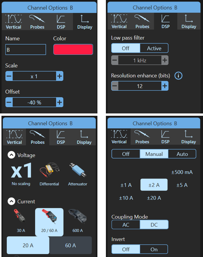
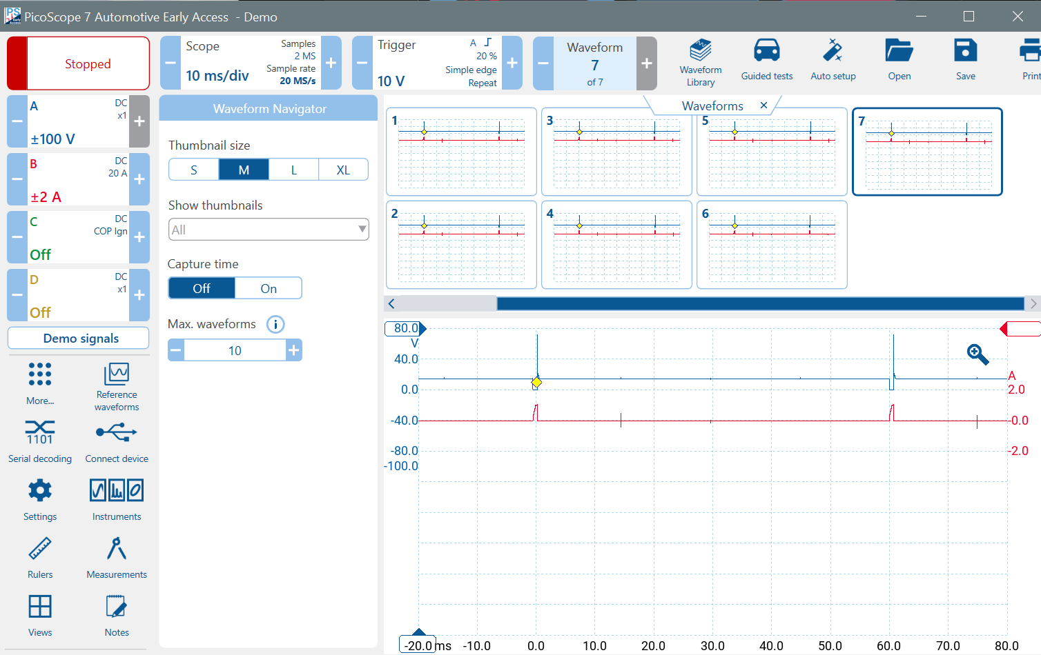
Click on the Channel B Control and set it up as follows:
Remember, always choose the Probe first if you are not using PicoBNC+.
- Probes Tab
- Select the PICO-TA018 20/60A Current Probe and then 20 A
- Vertical Tab
- Select ±2A
- Invert Off
- Display Tab
- Scale x1
- Offset 0%
- DSP Tab
- Low-Pass Filter Off
- Resolution-Enhance 12 bits
Analyse both Injector Waveforms
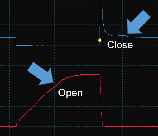
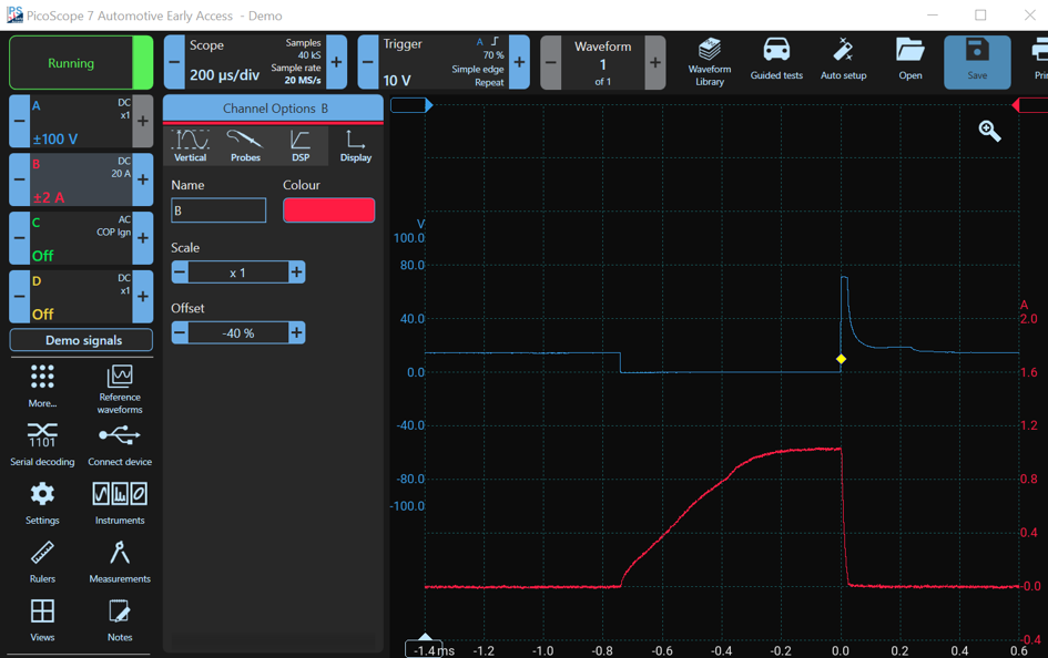
The injector current is the red waveform on Channel B and the injector voltage is the blue waveform on Channel A.
Notice how the rising edge is slightly concave because the pintle moved, opening the injector, and the inductance changed. The effect is quite subtle in this example but can be much more pronounced in other injectors.
In this example, the injector opened at about -0.4 ms (800 mA) and closed at about +0.25 ms. It was open for about 0.65 ms. Also notice that current was limited to about one amp, either by the injector's coil resistance or by the ECU driver.
Scaling and Moving a Waveform
If you want to fit the waveforms onto the display or to increase their size if they are too small, you can change the scaling. This does not change the sampling resolution (vertical) but merely changes the size on the display. Click on the Channel A and B controls, select Display, and change the Scale to x0.5. Notice how the scales on the sides of the display change to match the new scale factor. Now move the channels up (Offset). This leaves space for Channels C and D.
If you are using a mouse, you can scale by holding the mouse pointer over the scale and rolling the mouse wheel. You can move (offset) the waveforms by dragging the appropriate scale up and down.
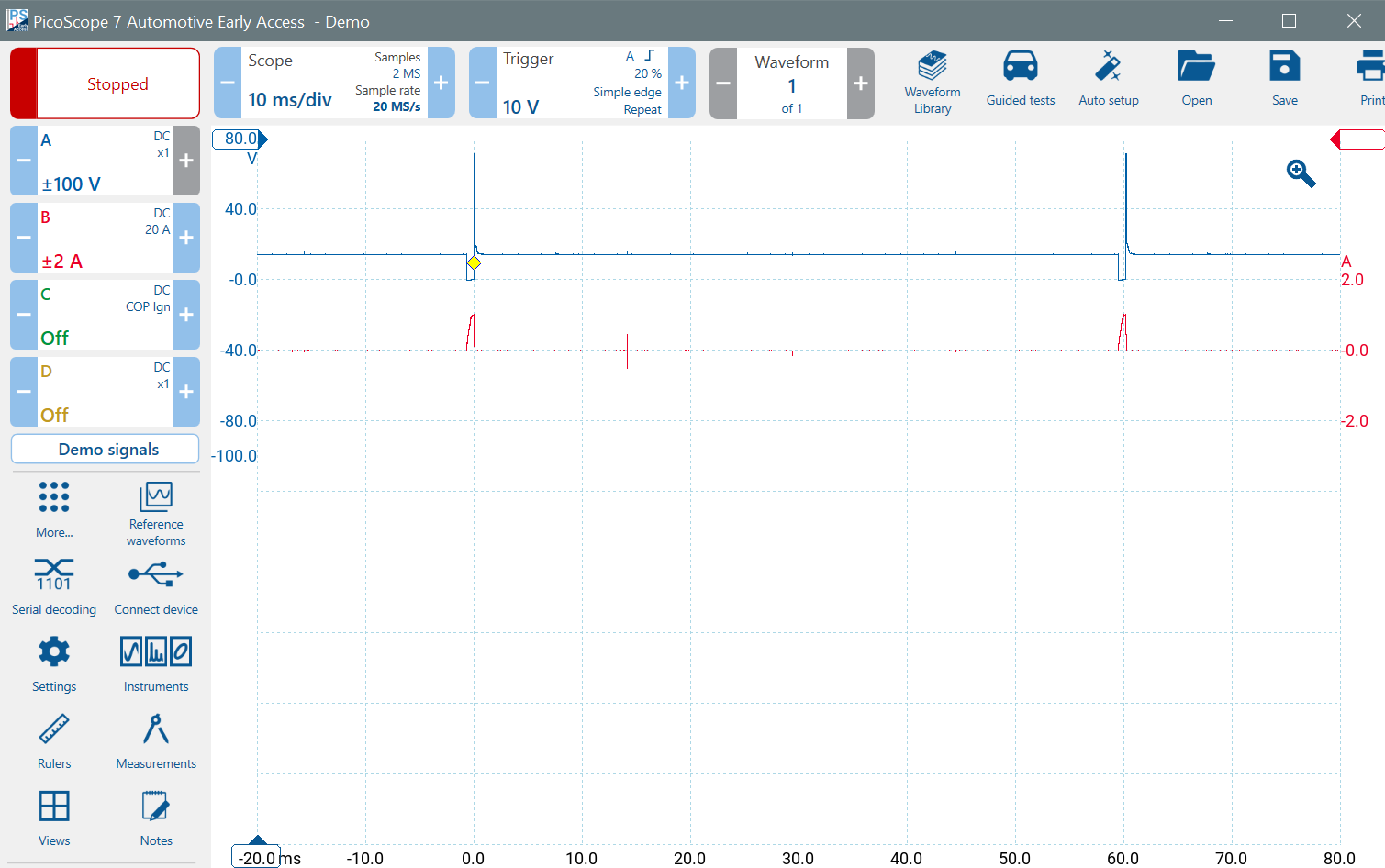
Notice the little spikes on the Channel A waveform. These are due to interference caused by ignition. We will examine the ignition waveforms and how they relate to the crankshaft sensor on the next page.
Waveform Buffers
PicoScope can capture multiple waveforms. You can enable waveform buffers to capture previous waveforms. According to PicoScope's specifications, you can have up to 10,000 buffers. A more reasonable number is 10, so click on the Waveform Lozenge and change the Max. Waveforms to 10. Ensure that the scope is running to fill the buffers.
PicoScope 7 may change parameters automatically as you work to try to create the best image or setup. When Channel B is enabled, notice that the number of Waveform Buffers is 7. When you disable it, the enabled buffer count is reduced to only 3. (Remember to run to fill the buffers).
This may seem odd to you, because enabling another channel should produce more samples and leave less space in memory for waveform buffers. However, look at the Timebase control. PicoScope 7 has reduced the sample rate from 80 MS/s to 20 MS/s, and hence the number of samples from 8 MS to 2 MS. This reduced the space required and allowed more waveform buffers to be added.