


Setting a Trigger on PicoScope
A new Demo Mode Course has been created.
Setting a Trigger
Understanding Triggering your PicoScope.
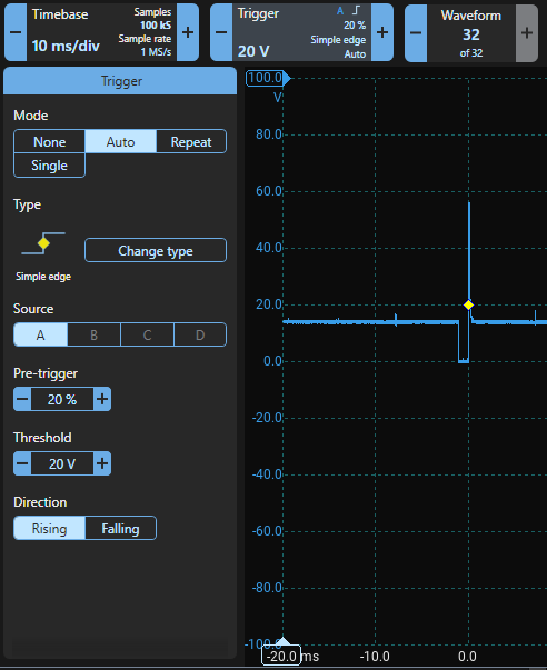
Once you have completed all the settings on the previous page then you should see the Channel A waveform with 0 V at the middle of the display when the scope is running. If you haven't set a trigger, the waveform will jump about and won't be stable. For now, set a simple trigger to stop the waveform from moving about:
- Click the Trigger Control;
- The Trigger Panel will appear;
- Choose Mode Auto;
- Change the type to Simple Edge;
- Choose A as the Source;
- Set the Pre-trigger to 20%;
- Set the threshold to 20 V; and
- Set Direction to Rising
These are the demo device's default values which are loaded when you restore factory settings and provide a good starting point. The waveform should stop jumping about, and with a timebase of 10 ms/div, you should see two injection events on the screen.
Understanding Triggering
An oscilloscope will try to display waveforms as quickly as possible if there is no triggering, so as soon as it is finished displaying one screen, it will start on the next. That means that the display and waveform might not be in sync and the waveform will appear to jump backwards and forwards.
Triggering puts you in control. When you set a trigger:
- You tell the scope to only display waveforms when conditions you specify are met
- You place the trigger on the display
- You control where and when the scope displays the waveform
- You can even decide to see events leading up to the trigger
Adjusting the Trigger
Notice that in the image, there is a yellow diamond on the Channel A waveform. It appears when simple edge triggering is enabled and shows where the scope is triggering. The scope has been set up to trigger (display the waveform) when Channel A passes through 20 V in a rising direction. You can move the trigger diamond manually by dragging it, or you can set up the trigger precisely by clicking on the Trigger control at the top of the screen.
Notice that the timescale at the bottom of the screen changes so that 0.0 is directly below the trigger point. The trigger is at 20% from the left of the screen — the pre-trigger percentage.
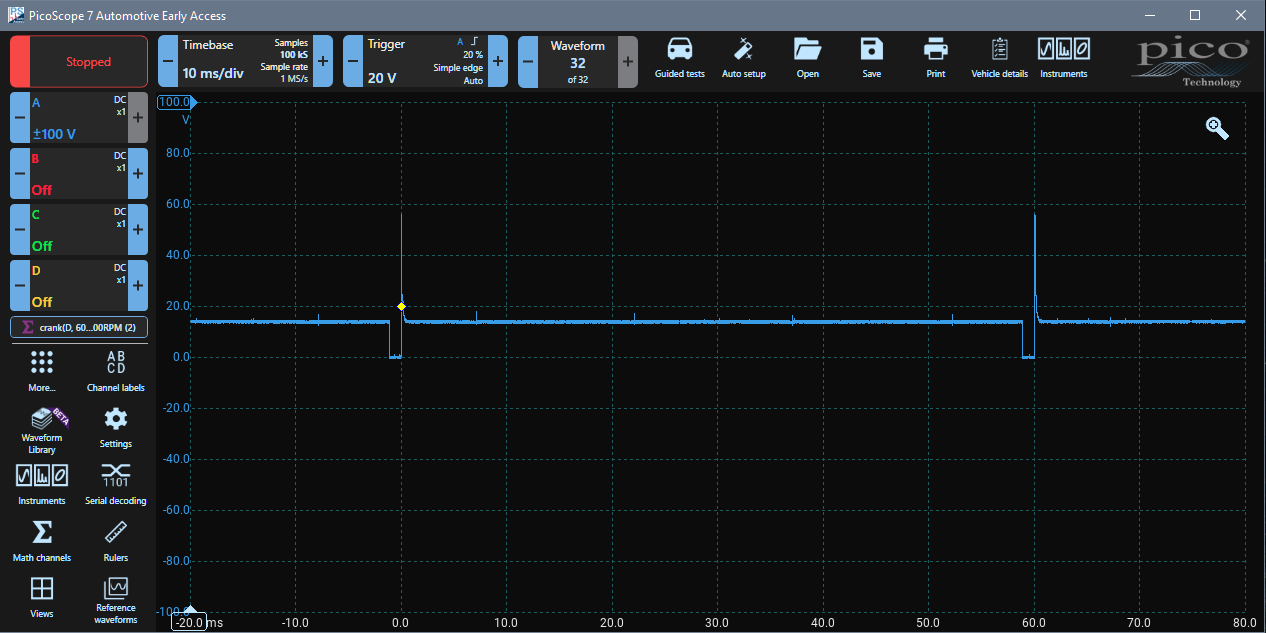
PicoScope is a storage scope which means that it saves the data it captures in memory. Notice that the scope displays waveform data that was captured and saved both before and after the trigger. This means that you can examine conditions and events that led up to and that possibly caused the trigger point to occur — an extremely valuable diagnostic tool.
Dragging the Trigger
Click and hold on the trigger diamond and drag it to 10.0 V (Blue Y Axis) and to the middle of the screen, horizontally.
The trigger panel will update and show that the trigger is at 50%, and the scope triggers when Channel A rises and passes through 10 V. You can also set the position manually by clicking on the trigger control. Notice that the X-Axis has been updated and 0.0 is now at the middle (50%) of the screen below the diamond and the waveform has shifted and the injector event is now at the centre of the screen. Half of the displayed waveform is before the trigger (i.e. the pre-trigger is 50%).
Changing the Direction and Timebase then Panning to fit
Click the Trigger Control and the Trigger Menu Panel appears. Change the direction to falling and the waveform will move slightly to the right because it is triggered on the falling edge. Click Timebase and change it to 200 μS per division. The injection event gets much wider and more detailed and extends off the screen to the right.
Change the trigger to Rising, and now the event starts left of the screen. Click on Trigger and change the pre-trigger to 70%. The entire injection event is displayed in detail across the screen. Remember that you can use the mouse and drag the trigger diamond to adjust the trigger quickly.
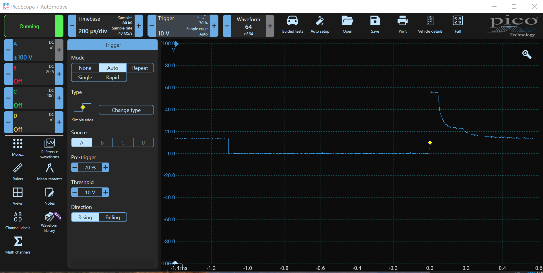
Now you can clearly see where the ECU pulls the injector voltage low to open it, the clipped, back-EMF spike when the current stopped and the voltage decay with the 'bump' showing when the injector pintle closed. Notice that we haven't zoomed (zoom is described on the next page) into the display. Using this technique, we have maximised the scope's resolution for the waveform being examined whilst we magnify the injection event to reveal fine detail.
Understanding and Using the Trigger Window
Click on the Trigger Control and the Trigger Menu Panel appears.
Understanding Trigger Modes
There are four trigger modes. These determine how and when the scope displays the waveform.
Trigger Mode None
Trigger Mode None switches off triggering. The PicoScope updates the screen as soon as the previous trace has been displayed. Click on None, and you will see that the injector event is no longer stable but appears in random locations depending on when the screen refresh started. Notice that the X Axis has moved the 0.0 to the left. There is no pre-trigger because there is no trigger.
With the timebase set to 200 μS per division, the injection event only appears occasionally, almost as a flash. Change the timebase to 20 ms per division, and you will see three or four trigger events moving about, randomly.
Trigger Mode Auto
In Auto Mode, the screen is redrawn whenever the trigger conditions are satisfied, but if not, the screen is refreshed automatically about once per second. Choose Auto and notice that the ignition event is stable. Now change the threshold to -40 V (well below the minimum of the blue waveform which means that the trigger conditions will never be satisfied). You will notice that the screen refreshes about once per second in a random fashion similar to no trigger.
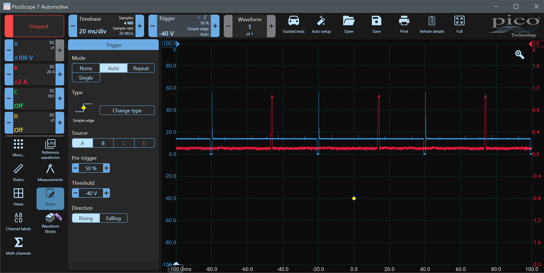
Effect of Auto Triggering on Multiple Channels
Be cautious when using Auto triggering (where the waveform is refreshed automatically) because multiple channels (e.g. Channel A and B waveforms) do not necessarily coincide in time as the channels may not be redrawn simultaneously. This can lead to errors in interpretation of the waveform. This effect is not unique to PicoScope 7, it also occurs in PicoScope 6 and many other oscilloscopes.
Channel A is the Injector Voltage and Channel B is the injector current. The two should happen at exactly the same time. Click on the Channel B Control and set Channel B to ±2 A. With Auto Triggering set on Channel A at -40 V, you will see that Channel A and B do not coincide in time as they should.
Click on the Trigger Control and change the trigger level to +10V. Channels A and B now coincide correctly because the scope is being triggered. Unlike Auto, this effect does not occur when triggering is set to None. Change the Trigger Mode to None and notice that the two channels coincide as they should.
Trigger Mode Repeat
Repeat Trigger Mode does not refresh the display automatically. The signal is displayed (refreshed) only if the trigger conditions are met. Click on Repeat, and you will see that the refresh stops completely because the trigger conditions are still not being met.
Now change the Threshold from -40 V to 5 V, and refreshing resumes.
Trigger Mode Single Shot
This mode tells PicoScope to refresh once only when the trigger conditions are fulfilled and then to stop running so that you can examine the waveform. Click Single and the scope will stop running. Notice that the Running Stopped Button has turned red.
Now change the threshold to -40 V agan and click the red Running Stopped Button at the top left. The PicoScope starts to run (the button turns green), but the screen doesn't update. Now drag the trigger diamond up until it is above 0.0 V on Channel A (i.e. the trigger conditions will be met), and the PicoScope will immediately update the waveform once and stop. You need to click the Stopped Button to capture another waveform.
Trigger Types
There are many types of triggers. They can be used to isolate certain conditions so that you can focus on them. We are currently using the most popular, a simple edge trigger - i.e. the level rises or falls past a certain point. Click on Change Type to see the various trigger types available.
- Simple Edge
- Advanced Edge
- Window
- Interval
- Pulse Width
- Window Pulse Width
- Level Dropout
- Window Dropout
- Logic
Further discussion of these is beyond the scope of this introduction because they cannot be demonstrated effectively using the demo device. However, here is a video from Pico's Test and Measurement Department that shows you the basics:
Please note that although most of the modes in the video do apply to automotive, some trigger modes such as ETS and MSO aren't applicable to automotive scopes.
Trigger Source Channel
Try changing the Trigger Source to B. Set the Pre-trigger to 60%, the Threshold to 400 mA and the Direction to Falling. Change the Mode to Repeat and start PicoScope running. You will now see PicoScope triggering on Channel B.