


Top-10 Test 2: Ignition Coil-on-Plug (COP) Testing
Test 2: Ignition Coil on Plug
The purpose of this test is to investigate and examine the secondary voltage from a Coil on Plug (COP) ignition unit using a COP Probe.
How to Perform the Test
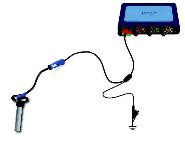
- Connect the COP Signal Probe to Channel A of the PicoScope.
- Connect the clamp on the COP probe to the engine block ensuring that there is s good earth.
- Use the Guided Test to provide information and to set up the PicoScope for you:
- Click on the Guided Tests button at the top of the PicoScope 7 screen to open Guided Tests;
- Choose the Yellow Ignition Button
- Click on Coil on Plug
- Choose Secondary (COP probe, mV scaled)
- Click Guide and Settings File
- Start the scope to see live data
- Place the foot of the COP probe squarely on top of the COP unit being tested
- TIP: You can move the COP probe around to find the best signal
- With your waveform on screen, stop the scope
- Turn off the engine
- Use the Waveform Buffer, Zoom and Measurements Tools to examine the waveform
Video Commentary
The customer reported a suspected COP fault after a misfire. The extremely high voltages in an ignition coil can cause the internal insulation to break down. This can reduce spark intensity or extinguish the spark completely.
The video shows how the insulation has broken down and the high-tension secondary voltage is finding an alternative path (leaking) within the coil.
Connect: Connect the Coil-On-Plug and Signal Probe to the PicoScope and always earth it to the vehicle.
Run: Start the engine which should be idling for this test. Start PicoScope and place the end of the Coil on Plug (COP) probe on the top of the coil pack to capture the signal. Move it around to get the best, clear signal. Test each of the coil packs sequentially.
Read: Examine the waveform, look for the initial and final oscillations, a good dwell time, ionising spike and burn time.
When you find a good waveform, set it as a reference so that you can compare it to the other units.
Comparison of the reference and cylinder 1 waveform shows that the dwell time is missing, and as there is no ionising spike, no spark or burn time occurred. There is an obvious problem with this unit.
After replacement of the coil pack, the test was repeated confirming the fix with a good waveform on the new coil.
Waveform Notes
The secondary waveform shows the length of time for which the HT flows across the spark plug electrodes after the initial peak of voltage required to jump the plug gap. This time is referred to as the 'burn time' or the 'spark duration'. The voltage during the burn time should stay relatively constant, dipping at the end into the 'coil oscillation' period.
The coil oscillation should display at least 4-peaks (upper and lower). A loss of peaks indicates that the coil may need replacing. The period between the coil operation and the next 'drop down' is when the coil is at rest between spark events. The 'drop down' (at the beginning of the cycle) is caused by the current starting to flow in the coil. A small oscillation should be present at the beginning of this period, also known as the 'dwell time' or 'negative polarity peak'.
The energy (in the form of a magnetic field) builds up in the coil during the dwell time and the current ramps up. When the current is interrupted, the HT spike is generated that ionises the air in the spark gap, at which time the 'burn time' begins.
Plug firing voltage is rather high, around 10 to 14 kV. Low plug firing voltage will not ionise the air in the spark gap, which means that ignition will not occur.
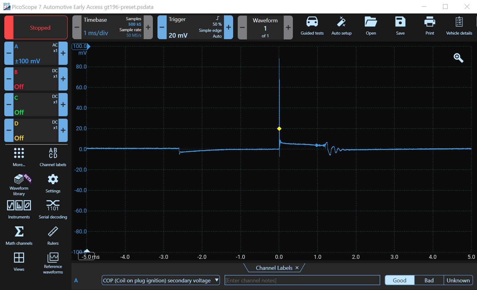
Good Waveform
This waveform clearly shows the 'dwell time', the period during which the current builds up in the coil. The high-voltage ignition spike is next, which causes the air between the plug's electrodes to ionise. Current then flows during the burn time until the energy in the coil is exhausted. Notice the oscillations at the end which should be present if the coil is good.
Accessories
Use the new PICO-TA398 with the newer PicoBNC+ PicoScopes and the PICO-PP357 with the older BNC PicoScopes.
- PICO-TA398 COP Probe with PicoBNC+
- PICO-PP357 COP Probe set with BNC