


Top-10 Test 3: Wiring Loom Connection Faults — Wiggle Test
Test 3: Wiring Loom Connection Faults — the Wiggle Test
The purpose of this test is to quickly identify wiring or connection faults by wiggling a wire and observing the waveforms on the screen. This is useful when you suspect an intermittent fault with a signal (on an already existing connection).
Multi-meters update only once or twice per second, which means that an intermittent connection might be missed. Using a scope solves this problem.
The test can be performed using test leads or probes whilst looking at real-life signals, or you can use the resistance test lead without any power being applied from the vehicle. Both methods are discussed. You can also use the resistance probe to detect intermittent shorts between adjacent wires.
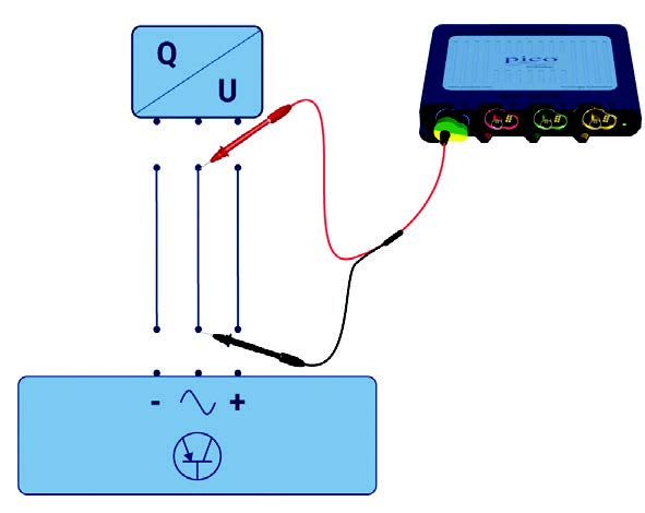
How to perform the test using the Resistance Probe
Remember that the PICO-TA432 Resistance Lead is like the 'ohm-meter' setting in your multi-meter. You should not have power applied to the circuit when using the resistance lead. If there is power, then perform the test using your test leads (see below).
- This test is used when you suspect or have spotted an intermittent fault with a signal (so a connection is already made);
- Use the Guided Test to provide information and to set up the PicoScope for you:
- Click on the Guided Tests button at the top of the PicoScope 7 screen to open Guided Tests;
- Click on the grey 'System tests' button;
- Select 'Wiggle test (resistance)';
- Click 'Wiggle Test';
- Click the 'Guide and settings file' button.
- Disconnect the part of the loom you want to test at each end and connect the resistance probe to each end of the circuit;
- Start PicoScope when you are ready to capture the signal and gently wiggle the wiring loom attached to the component;
- We recommend reducing the capture rate to make it easier to spot problems within a single screen capture. You can use masks and alarms to detect when signals go outside normal limits;
- Stop PicoScope and scroll back through the buffers. Wiring or connection faults will often create an inconsistent pattern, as illustrated in the example. In this case, it turned out that a fault in the wiring loom was causing an ignition misfire. Remember to retest after the repair to make sure that you have a reliable fix.
How to perform the test using Test Leads
The test can also be performed whilst monitoring a voltage or a signal and checking for disturbances when the loom is wiggled.
- Use a test lead to detect voltage at the suspect component;
- Remember to always use an attenuator (PICO-TA197) or a 10x probe (PICO-TA499) if you are testing high-voltage signals such as primary ignition;
- Start the PicoSCope when you are ready to capture the signal;
- We recommend reducing the capture rate to make a single-screen capture;
- You can set up masks and alarms to automate detection when signals go outside their normal limits;
- Gently wiggle the wiring loom attached to the component;
- Stop the PicoScope and go through the data.
Video Commentary
In this test, the Camshaft sensor seems faulty but intermittent.
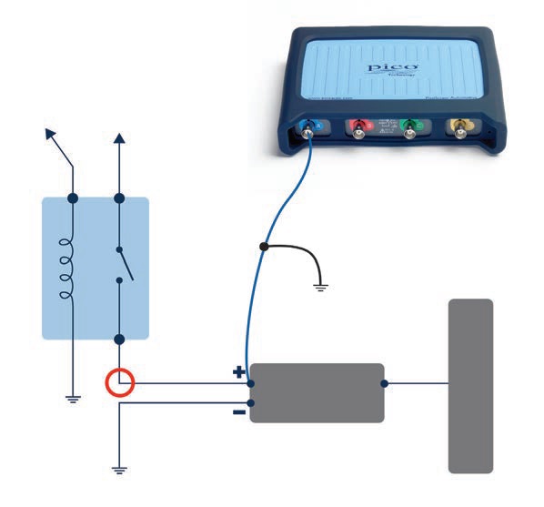
Connect: Use a Back-pinning Probe to connect to the Camshaft Sensor and ground the test lead as shown.
Run: Start PicoScope and the engine when you are ready to capture the signal and gently wiggle the wiring loom attached to the component.
We recommend reducing the capture rate to make it easier to spot problems within a single screen capture. Masks and alarms can be used to automate detection when signals go outside normal limits.
Read: Stop PicoScope and scroll back through the data with the buffer controls. Often wiring or connection faults will create an inconsistent pattern as illustrated in the example. The loom was compromised by chafing against a bolt causing an intermittent connection and short to earth.
Remember to retest after the repair to make sure that you have a reliable fix.
Waveform when using the Resistance Lead
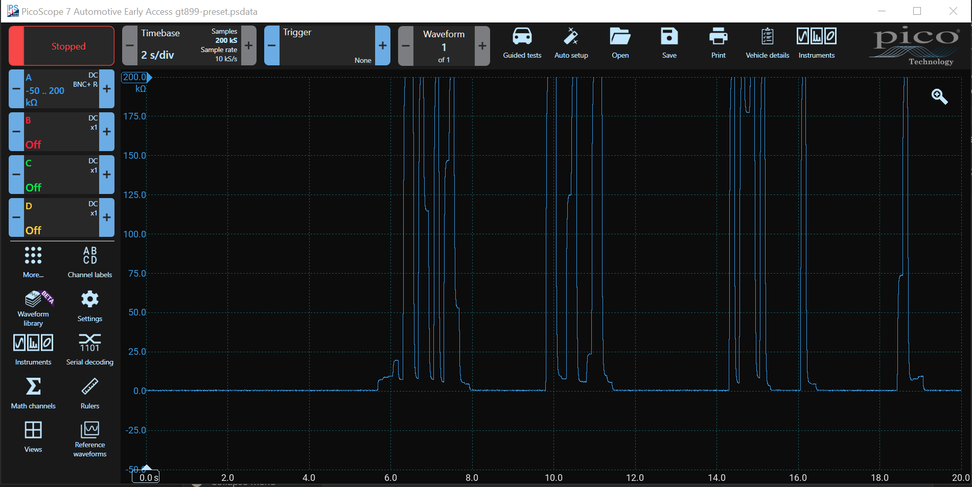
Wiggle Test — Finding a short or open circuit wiring fault
It is really simple to find broken or intermittent connections using the resistance probe with your PicoScope.
Running time: 3 min 21 s.
Accessories
The resistance lead: PICO-TA432 is only available in PicoBNC+. Use the PICO-499 10:1 Probe, which is also PicoBNC+ with the newer PicoBNC+ PicoScopes, and the PICO-TA197 10:1 Attenuator with the older BNC PicoScopes when testing high voltages.
- PICO-TA432 PicoBNC+ Resistance Lead
- PICO-TA499 PicoBNC+ Automotive 10:1 Scope Probe & Adaptor
- PICO-TA197 10:1 Attenuator (BNC)