


PicoScope CAN Bus Testing
PicoScope CAN Bus Testing
CAN (Controller Area Network) Bus (a bus is a communication system that transfers data between or within a computer system) is a vehicle bus standard that enables efficient communication between multiple electronic control units (ECUs) within a vehicle.
It is essentially a digital network that allows various components, like the engine, transmission, and sensors, to share information with each other. This communication is crucial for the proper functioning and coordination of a vehicle's systems.
We will start with a brief introduction and overview of CAN, and then we will use demo signals to introduce CAN testing with a PicoScope.
CAN Bus Physical Structure
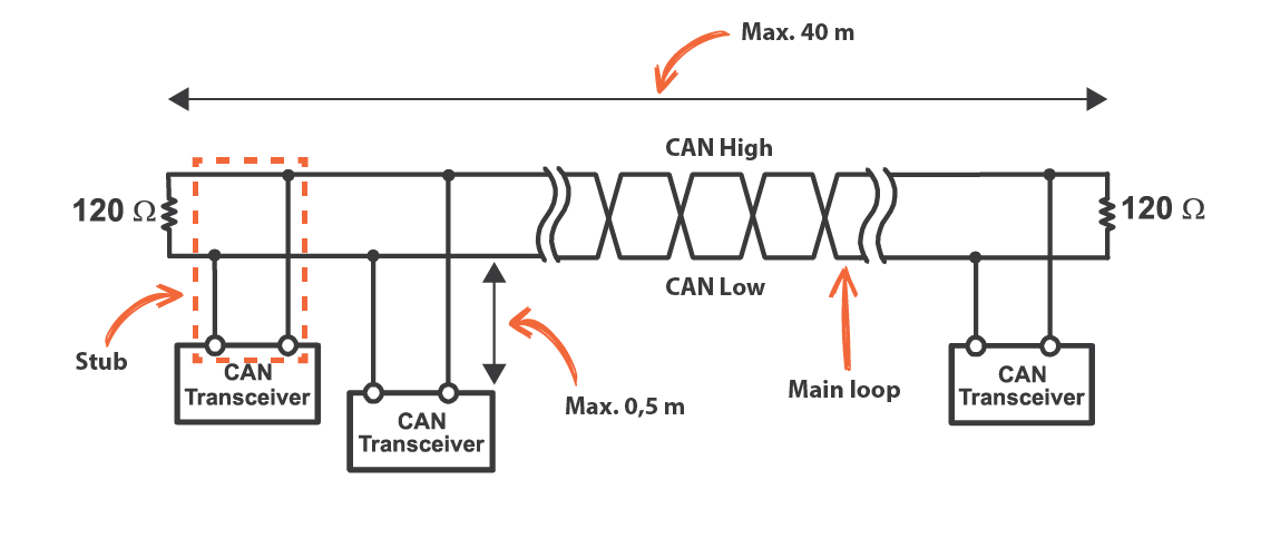
The CAN bus is simply a twisted pair of wires that links the ECUs in a daisy-chain fashion. The length must be less than 40 metres and no branches are allowed. Stubs, which are short connections to the ECUs, are allowed, but they may not exceed 500 mm. At the two ends of the network, a 120-ohm resistor is required for termination. Note that only two terminations are allowed, which is one reason why branches are not allowed.
Understanding CAN Signals
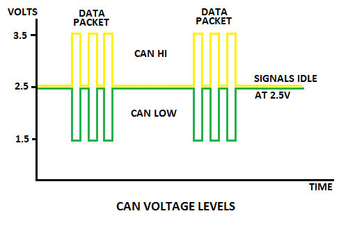
CAN is a differential bus. This means that when one signal goes positive, the other goes negative. A CAN bus sends digital data (ones and zeros), and when a one is sent, both CAN-H and CAN-L are inactive and are at 2.5 V. This is called a recessive bit.
When a zero is sent, CAN-H is set to 3.5 V, and CAN-L is set to 1.5 V. This is called a dominant bit. Keep in mind that more than one transmitter can send data at the same time. If one or more transmitters send a dominant bit (0) and others send a recessive bit (1), then, as the name implies, the dominant bit overrides the recessive bit and all receivers will receive the dominant bit (0). This is called a collision.
This is a logical AND function. A recessive bit (1) only occurs if ALL ECUs are idle or sending a recessive bit (1).
CAN Bus Addressing and Priority
CAN is a common-media bus which means that all receivers receive all messages simultaneously. The CAN bus uses an innovative scheme to resolve contention (more than one transmitter wanting to send at the same time). Every ECU has a set of unique message source addresses that not only show where the message originated but also show what type of message is being sent.
Using the overriding dominant bits (0) in the ECU's message source address, messages with lower source addresses have priority and will always be sent before messages with higher source addresses.
Understanding Terminations
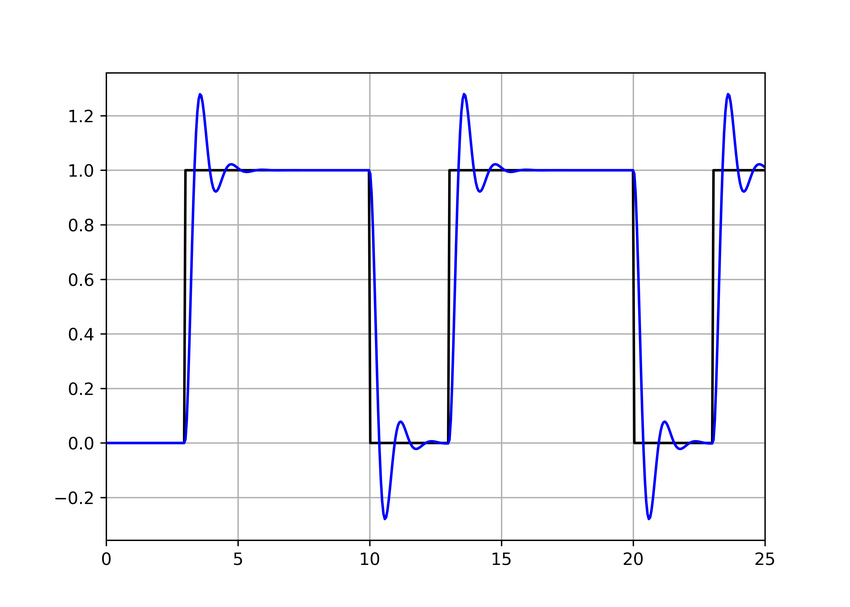
When a high-speed signal travels down a wire and reaches the end, it tends to bounce off the end very much like an acoustic echo. The signal then travels to the other end and bounces again, producing ringing. Severe ringing can distort the signal to the point where data errors occur.
If you place a termination resistor at the end of the cable, which is matched to the impedance of the cable (roughly 120 ohms for a twisted pair), the energy is absorbed and does not reflect back. Ringing is reduced and data integrity is enhanced.
Static CAN Bus Testing with a Multi-Meter
Ensure that power is off, or you might damage your multi-meter or resistance probe. Check for voltage on the CAN bus to ground with a voltmeter or use your PicoScope.
You can use a multi-meter or the PicoScope resistance probe to measure resistance. The values you get will vary from those mentioned below as there is a tolerance (an acceptable deviation from the specified resistance). Between 5 and 10% variation or tolerance is acceptable.
Measure the resistance between CAN-H and CAN-L to ground. You might expect an open circuit, but remember that when the CAN bus is idle, it is at 2.5 V. A pair of resistors is used as a voltage divider to hold it there, so you may measure around 300 ohms (typical, not a specified value, and could be very different) between the CAN wires and ground. If the value is very low, there might be a short to ground.
Measure the resistance of the CAN network between CAH-H and CAN-L. If the resistance is very high or open circuit, then you are completely disconnected. If the resistance is about 120 ohms, then only one terminator is being detected and the CAN network is likely to have a break. If 60 ohms is measured, then both resistors are present and the CAN network is complete as two 120 ohm resistors in parallel will measure as 60 ohms.
Connecting to a CAN bus
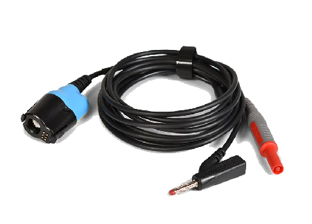
Technicians often use standard test leads to connect their PicoScope to a CAN Bus. This was done when capturing the demo signals used in this tutorial and in many CAN Bus videos. If you look closely at the signals below, you will see ringing. This is not good practice. CAN is really a medium-speed communication standard, so using the incorrect lead can work, even though some distortion of the signal results.
When higher speed standards such as CAN-FD, and especially Flexray are tested, the addition of a test lead can cause a good bus to fail.
If you recall, the maximum stub length is 500 mm. Adding a 3 or 5 m test-lead to the CAN Bus violates this rule and creates an unterminated branch. The PicoScope input impedance is 1 MΩ (no effective termination), and ringing is introduced by the test lead. Furthermore, the test lead has high capacitance that loads the bus and reduces the bandwidth.
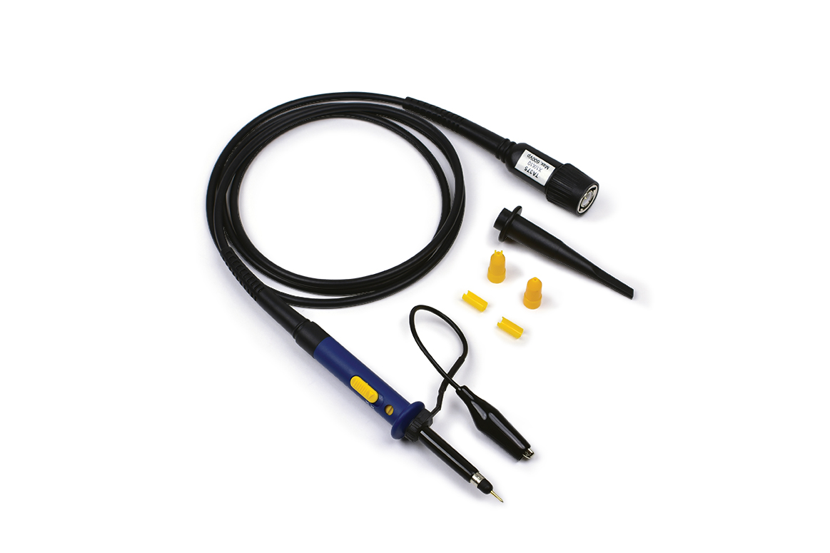
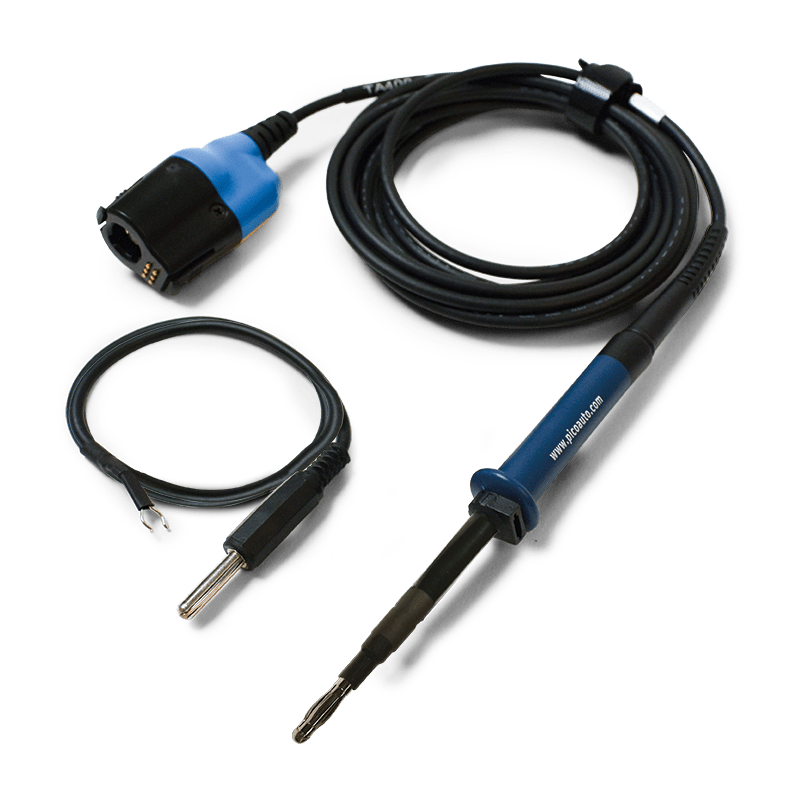
However, all is not lost! The solution is to use a 10:1 probe. If you have a BNC PicoScope (like the 4823 or 4425), then a pair of PICO-TA375 Scope Probes set at 10:1 will work well. If you are using a PicoBNC+ PicoScope (e.g. the 4425A), then use a pair of PICO-TA499 (old version) or PICO-TA506 (new version) 10:1 probes.
These probes have a 9 MΩ resistor at the tip and isolate both the length and the capacitance of the test lead from the bus.
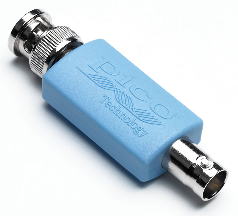
Note: Using attenuators (e.g. PICO-TA197) with test leads does not work. The attenuators are installed at the PicoScope end of the test leads and therefore do not isolate either the capacitance or the length of the test leads from the CAN bus.
Examining CAN Signals in Demo Mode
The new Demo Mode includes CAN signals. Both CAN-H and CAN-L are available, and you should assign them to channels A & B (see below) so that you can learn how to test CAN.
A new feature in the latest PicoScope 7 software is Default Setup (currently only available in the latest Early Access edition). Click More... to find it and click on it. That will reset the PicoScope 7 software to its defaults. Alternatively, you can use Settings and set Factory Settings and restart.
Click the Demo signals button and change the type of Channel A to CAN-H and Channel B to CAN-L.
Change both Channel A & B probes to x1 and set vertical to ±5V on both Channels. Turn off Channels C & D. Ensure that the scaling is x1 and the offset is 0. Set the Time Base to 100 μs per division to start.
Remember to switch off all hardware and DSP filtering on the channels, or the fast CAN signals will be filtered out.
Now the waveform may jump about because there is no trigger. You can stop the PicoScope to examine the waveforms.

Foreground and Background Channels
Notice how in the image above, Channel B (red) seems to be in front of Channel A (blue), where they overlap. This can be a problem if you want to examine a particular channel, and it is hidden by the other channels. Click on the blue scale on the left, and Channel A will come to the front. Click on the red scale, and Channel B will come to the front, again. This works even if the PicoScope is stopped.

Next we will learn how the CAN protocol rejects noise and how to use the PicoScope to both detect noise and to reject noise for accurate decoding of CAN data.
Also, visit our CAN Bus Videos Page.