


Top-10 Test 4: Injector Voltage and Current
Test 4: Injector Current and Voltage
There are many ways to drive an injector. Two different tests are presented. The first test only measures current through a piezo injector. This injector is opened using a positive current pulse and is closed by a negative current pulse. Multiple injection pulses (defined as a positive current pulse to open the injector and a negative current pulse to close it) can occur. Notice how the time between the open and close current pulse is varied to determine how long the injector remains open.
Some injector drivers have even more sophisticated control schemes which use multiple voltages and currents:
- a high voltage to open the injector;
- a PWM controlled current to limit dissipation whilst the injector is open; and
- reversed high voltage to stop current flow, to close the injector quickly.
An example of this type of waveform can be seen on the What is Oscilloscope Diagnostics page.
The second test (below) is much simpler. An MPI injector is opened when electrical current flows through it, and a spring closes it when the current stops flowing. However, a great deal of information can be gleaned from its waveform.
Common Rail Diesel Bosch Piezo Injector Current Test
The purpose of this test is to check the actuation current within a Bosch-type Common Rail Diesel (CRD) Piezo Injector.
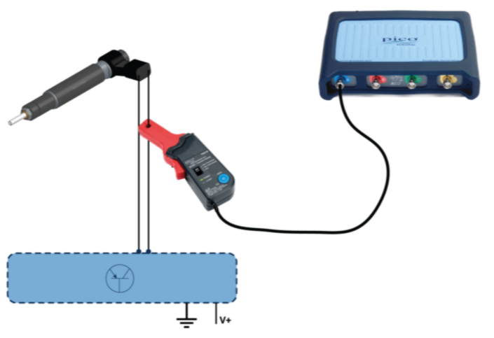
- Connect a low-amp clamp to Channel A;
- Select the 20A Scale and zero the clamp (not necessary when using PicoBNC+); or
- Use the guided test to set up the scope for you:
- Click on Guided Tests in PicoScope 7;
- Select the Green Actuator Button;
- Click 'Injector (diesel)';
- Choose 'CRD (Bosch) piezo injector';
- Click the 'Guide and Settings File' button.
- If you use the guided test above, then the scope will be set up with a known good waveform displayed;
- Start the scope to see live data;
- Vary the accelerator pedal to see idle acceleration and overrun injector waveforms;
- Stop the scope;
- Turn off the engine;
- Use the Waveform Buffer, Zoom and Measurements tools to examine your waveform.
Waveform Analysis
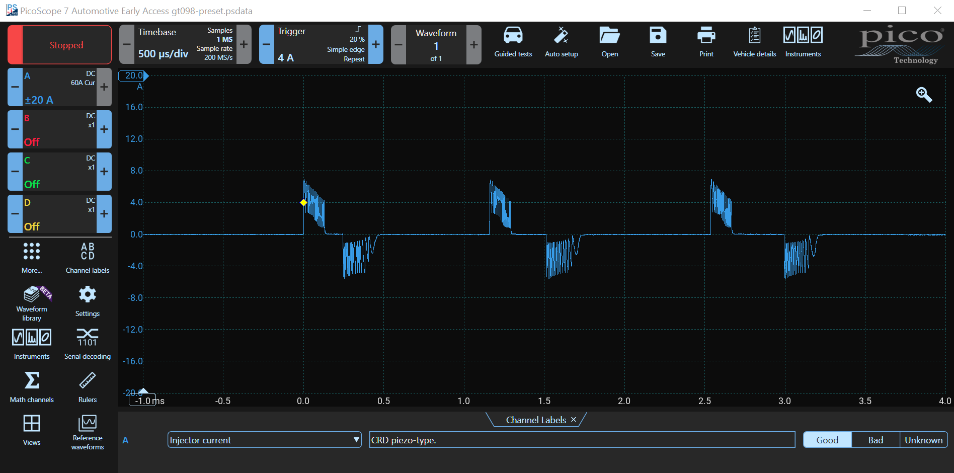
One or more pairs of positive and negative current pulses which respectively open and close the injector can be seen at idle. They have amplitudes of about ±7A. Although the voltage is not shown in this test, please note that Piezo Injectors use high voltages — about 100 to 120 V — to actuate.
- The first injection event is called the Pilot Injection, during which time, a small amount of fuel is delivered to better regulate (slow) the build-up of combustion pressure, thereby reducing diesel knock. Sometimes there can be more than one Pilot Injection event.
- The next injection pulse is called the Main Injection Pulse is when fuel to be burned and produce power is introduced. The width of this injection pulse varies depending on the quantity of fuel required.
- The last injection event is called the Post Injection and adds a small amount of fuel to assist with exhaust gas treatment (DPF). This pulse may or may not be present, and sometimes more than one pulse occurs depending on the vehicle.
During idle, three sets are often seen with the time between the open and close current pulses on the second (or third) injection event increasing to allow more fuel to be injected during acceleration.
During overrun, some, or even all, injection events can be omitted to reduce fuel supply.
The injection events occur at higher frequency at higher engine speeds.
Piezo Injector Guided Test Video
Pico has created a guided test showing you how to test a Piezo injector. Take heed of the warning not to disconnect a Piezo injector whilst the engine is running. A Piezo injector needs a closing pulse to close and can remain open, filling the cylinder with fuel if it is disconnected whilst it is open
MPI Injector Test
The video below shows how to perform a Multi-point Injector Test, measuring both voltage and current.
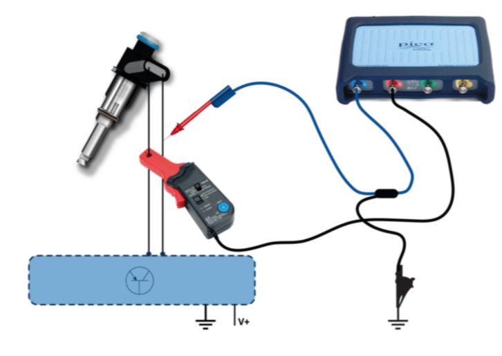
- Using a test lead, connect Channel A to the injector switched earth circuit (pulled low by the ECU);
- Connect a low-amp clamp to Channel B;
- Select ±100V on Channel A and 20 A on Channel B; or
- Use the guided test to set up the scope for you:
- Click on Guided Tests in PicoScope 7;
- Select the Green Actuator Button;
- Click 'Injector (gasoline)';
- Choose 'MPI injector voltage and current';
- Click the 'Guide and Settings File' button.
- Run the engine;
- Start the scope to see live data;
- Stop the scope once the waveform appears on the screen;
- Use the Waveform Buffer, Zoom and Measurement tools to examine your waveform.
The waveform and instructions on how to perform the Injector Current and Voltage test are loaded. The video below takes you through the procedure using the old PicoScope 6 software.
Probe Mismatch Detection
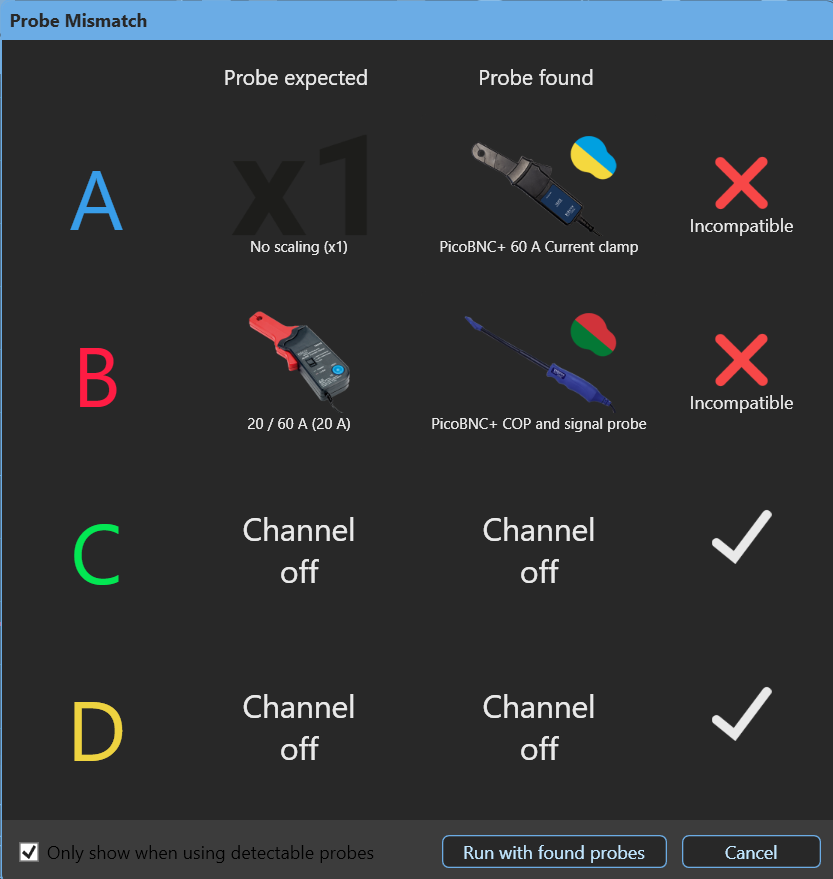
PicoScope 7 in conjunction with a PicoBNC+ oscilloscope like the 4425A will check the probes and inform you if you are not using the correct leads — a blue test lead on Channel A and a 60 A current clamp on Channel B.
I have intentionally plugged a 60A current probe into channel A and a COP Probe into channel B. When I started the scope, a probe mismatch notice appears. Correcting the probes corrected the problem, and the scope started running automatically.
If the image isn't clear, click on it to expand it.
Injector Current and Voltage Waveform Analysis
The waveform below shows injector voltage and current.
The voltage waveform is very different to the current waveform, and usually they are displayed simultaneously. In this waveform, Channel A shows the injector voltage and Channel B the current.
Voltage is applied to the injector — the ECU pulls the injector output low at time 0. The current in the injector does not increase instantly but starts to rise slowly because the injector is inductive (a coil).
Notice the bump in the current at about 1.2 ms which is caused by the change in inductance as the pintle (plunger) moved (opens). This is very obvious in this waveform, but often it is just a slight bump or change in the slope.
If the injector was purely inductive, the current would keep on rising, however, the coil windings have resistance, and sometimes the ECU drivers have current limiting. The current flattens out at about 2 ms due to one or both of these factors.
Once the correct quantity of fuel is injected, the driver switches off and the current ceases flowing at just after 4 ms.
Although the current waveform shows when the injector opened, there is no information about when it closed. Conversely, there is no information here about the valve opening in the voltage trace, which is why it is useful to see both traces, simultaneously.
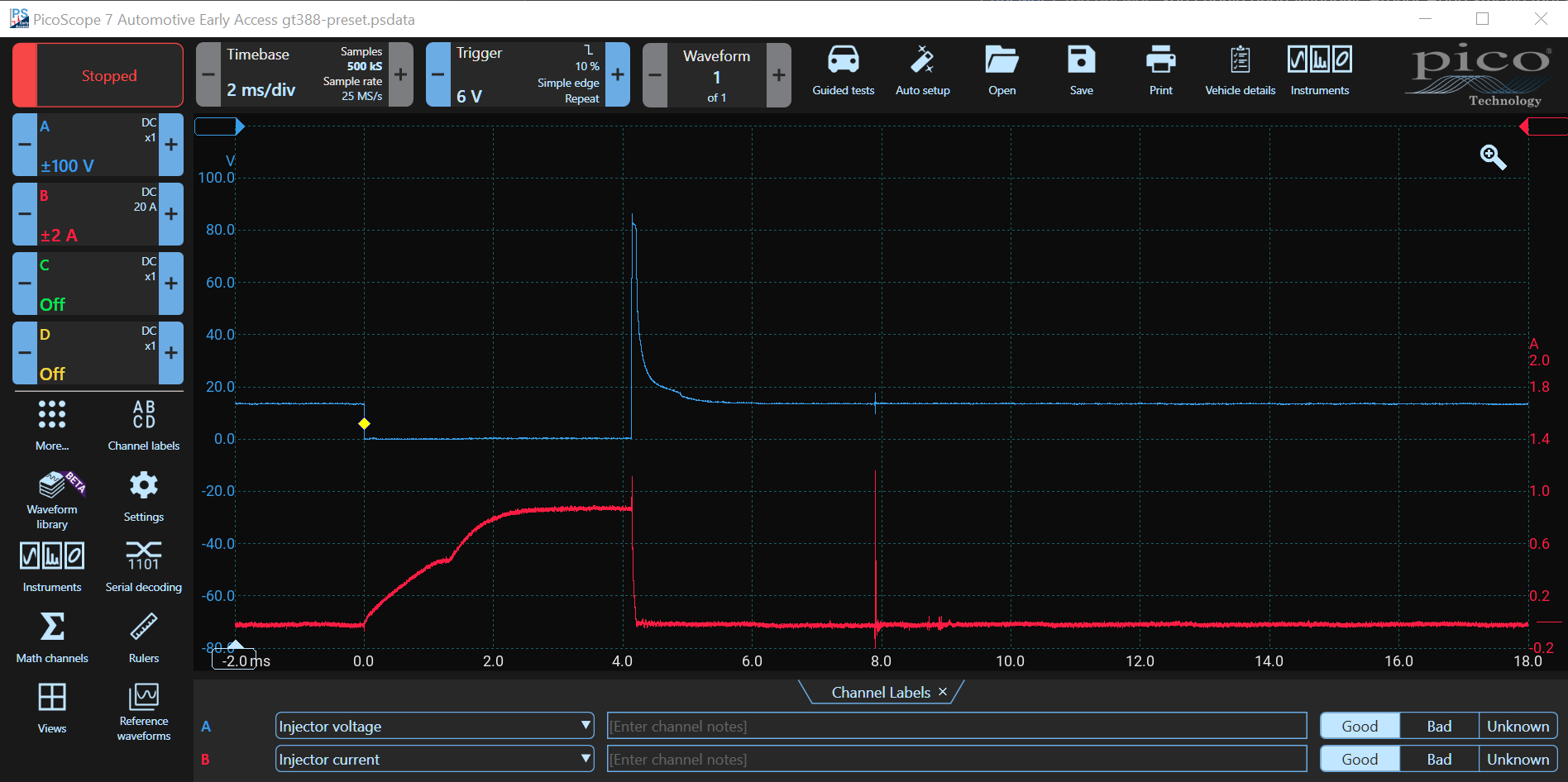
The voltage goes low as the driver switches on and pulls the injector to earth.
When sufficient fuel has been injected, the driver is switched off. The coil is inductive and therefore stores energy. When the current is abruptly terminated, the energy is converted into voltage which can produce a large spike.
The energy dissipates (usually in flyback or zener diodes in the driver), and the voltage spike is clipped (at 80 V in this waveform).
Notice the little bump in the voltage after the spike (at about 4.5 ms). This is due to the change in induction caused by the pintel (plunger) closing. Examining the two waveforms together shows exactly how long the injector was open.
Although not part of this discussion, it is interesting to note that the spike at just before 8 ms is probably interference from the spark ionisation spike, which provides an indication of when ignition occurred.
Petrol Direct Injection
A petrol direct injector is tested using a PicoScope. The voltage and current waveforms are analysed. The ECU controls both sides of the injector coil independently. The voltage on both sides and the current is measured in this test. Notice how the ECU starts with a high current to move the pintle. It then uses PWM to reduce the current to hold the pintle open (a lower holding current reduces power dissipation and heat). Then it applies a reverse voltage to collapse the magnetic field to close the injector as rapidly as possible.
Accessories
If you have a PicoBNC+ Oscilloscope such as the 4425A, then the PICO-TA473 current clamp is best. The economy PICO-TA018, the PicoTA234 and the premium PICO-TA189 are for the 4823, 8-channel PicoScope and for the older BNC PicoScopes.
Current Clamps- PICO-TA473 60A Current Clamp with PicoBNC+
- PICO-TA018 20 / 60 A, Economy Current Clamp (BNC)
- PICO-TA234 20 / 30 A, 20kHz Premium Current Clamp (BNC)
- PICO-TA189 30A 100 kHz Premium Large Jaw Current Clamp (BNC)