


PicoScope CAN Bus Noise Detection and Rejection
Sample Rate
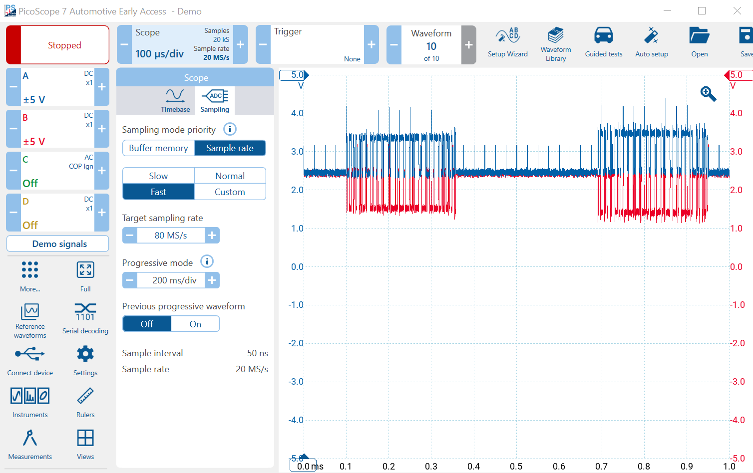
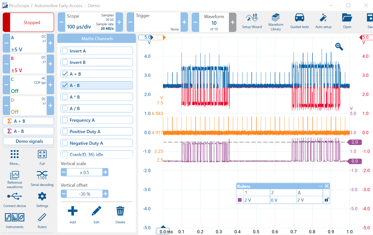
CAN data rates are relatively high, and a CAN bit at 500 kb/s is only 2 μs. The PicoScope defaults to a relatively low sample rate (e.g. 1 MS/s). Chose Sampling in the timebase menu and choose Fast. That will increase the requested sample rate to 80 MS/s. Note that the actual sample rate may be lower. In the image below, PicoScope has selected 20 MS/s. At 20 MS/s, there are 40 samples per bit, more than adequate for decoding and zooming.
The high sample rate will allow you to zoom into the waveform without a significant loss of resolution. Start and stop to recapture at the higher sample rate.
If the sample rate is too low, decoding will fail because bits can be distorted when they are not sampled properly. When you are sampling a square wave, like CAN, then you need far more samples per cycle, so it is better to err on the high sample rate side.
Remember that we are looking at demo signals here. That means that we are looking at a demo scope, not a real one. The maximum sample rate of the demo scope is only 20 MS/s. Real PicoScopes are much faster. The 4425A and 4225A can sample up to 400 MS/s, and the 4823 can sample up to 80 MS/s. When you use real PicoScopes, you will be able to analyse the CAN data much more accurately and with greater resolution.
CAN Bus Noise Detection and Rejection
A motor vehicle is a hostile place for electronic systems such as ECUs. To reduce the amount of wiring, automotive engineers use networks such as CAN to allow multiple signals to be carried on just two wires. The concept is called Time Division Multiplex or TDM. In CAN, each packet of data carries information between ECUs at high speed (typically half a million bits per second).
Sadly, if you have a problem, then multiple systems fail. It is therefore important to ensure that CAN is reliable and potential errors and problems are minimised.
One source of errors is electrical noise, also known as electromagnetic interference (EMI). There are many sources including ignition, injector drivers, other electronic systems (e.g. cellular phones), lightning, and even other nearby vehicles. Even a tiny 2 μs spike can change a bit and destroy a message.
The noise is often a magnetic or an electrostatic pulse, or an AC signal that impresses itself on (is picked up by) a conductor and changes the voltage of the signal on the conductor. Random changes are a real problem. The CAN network tries to reduce interference by using differential signalling.
By using a twisted pair, the conductors are physically very close together and any external noise is impressed on both signals, simultaneously.
Interference in the Demo CAN signal
If you zoom into the CAN demo signals, you will notice that there is some interference in the form of little spikes about 25 μs apart. Notice that the pulses affect CAN-H and CAN-L almost equally and in the same direction — a great example of spurious noise being induced on a real CAN network.
Using Addition to isolate any Noise and Interference
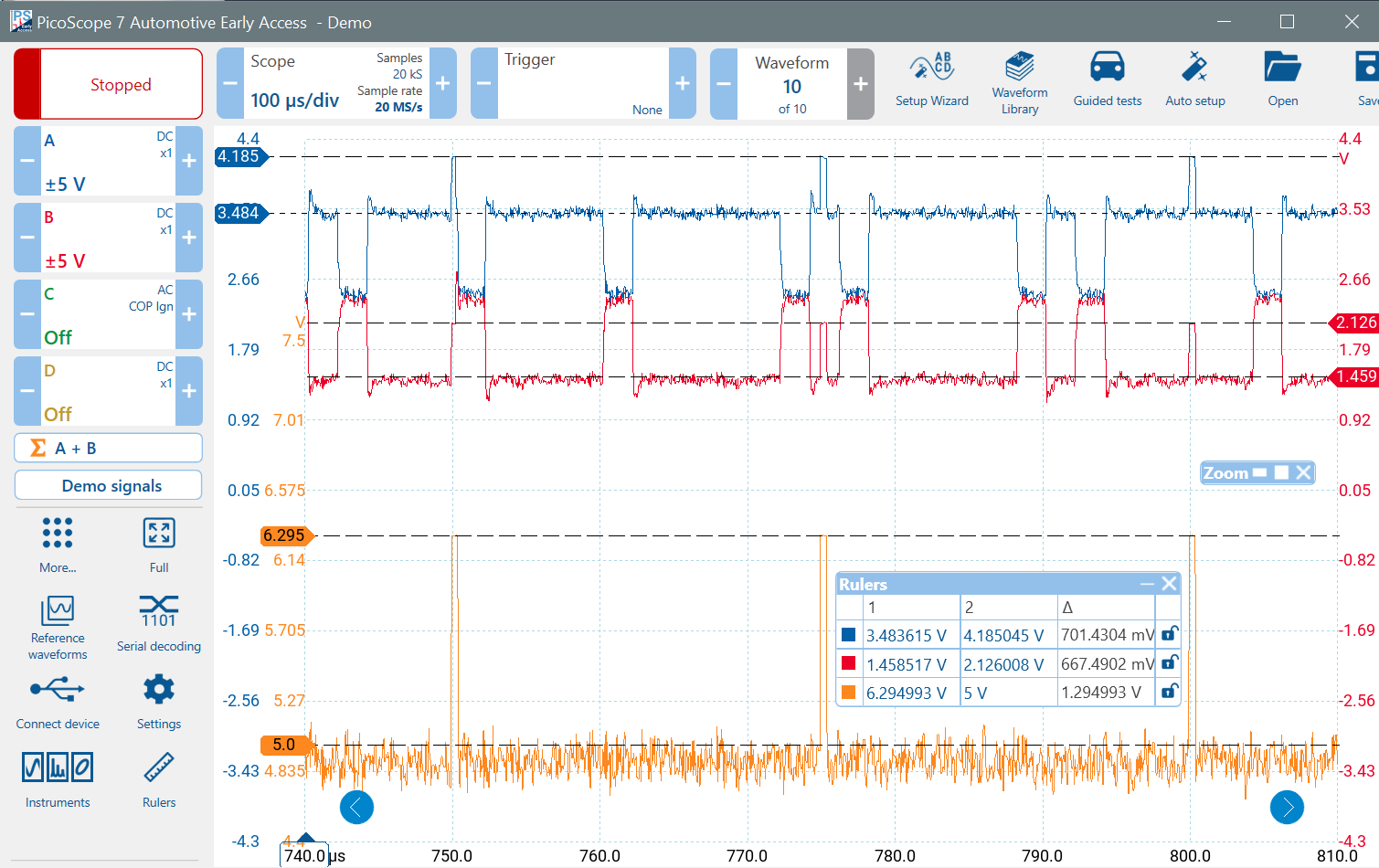
When a recessive CAN bit (1) is sent, both conductors are at 2.5 V. If you add the channels, the result is 5 V. When a dominant bit is sent, CAN-H is 3.5 V, and CAN-L is 1.5 V. The sum is also 5 V. If CAN-H and CAN-L are summed, a perfect CAN bus would produce a constant 5 V sum signal. Any noise induced on both conductors would be impressed on this 5 V sum signal at twice the noise amplitude (two wires). You can use this technique to find any common-mode interference on your CAN bus.
Click on the Maths Channel Icon (use More if it is not available). If the pre-defined Maths Channel A + B exists, then click on its check-box and enable it. If not, you can create an A + B channel yourself, as follows:
- Click on the + sign at the bottom
- Type A + B into the formula box at the top
- Click Next
- Choose a colour
- Change the range if necessary (2.5 to 7.5 will work well)
If you zoom into the waveform, you can clearly see the interference spikes on the 5 V waveform. The amplitude of the spikes on the 5 V waveform is about twice the amplitude of the spikes on CAN-H and CAN-L.
Scale (using your mouse wheel over the scale) and offset (dragging the scale) the sum waveform. You can also click on the A + B maths channel lozenge above Demo Signals and use the Vertical Scale and Offset boxes.
Now create an A - B maths channel and scale and offset it using your mouse or the offset boxes as described in the last paragraph. Notice that the interference spikes have been cancelled out completely along with most of the noise. You have a much cleaner (inverted) signal with amplitude of about 2 V. This shows how well noise cancellation works in differential signalling.
Determining the Data Rate
CAN systems usually transmit data at 500 kb/s but not always. Some systems are slower, e.g. 250 kb/s, and others such as CAN-FD have faster components. The data section of a CAN-FD packet is usually eight times the speed of the header section and can contain up to 64 bytes instead of CAN's maximum of eight bytes.
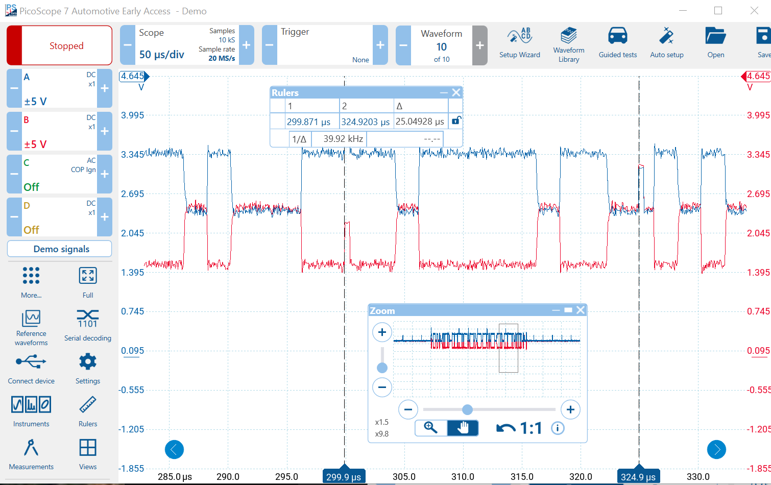
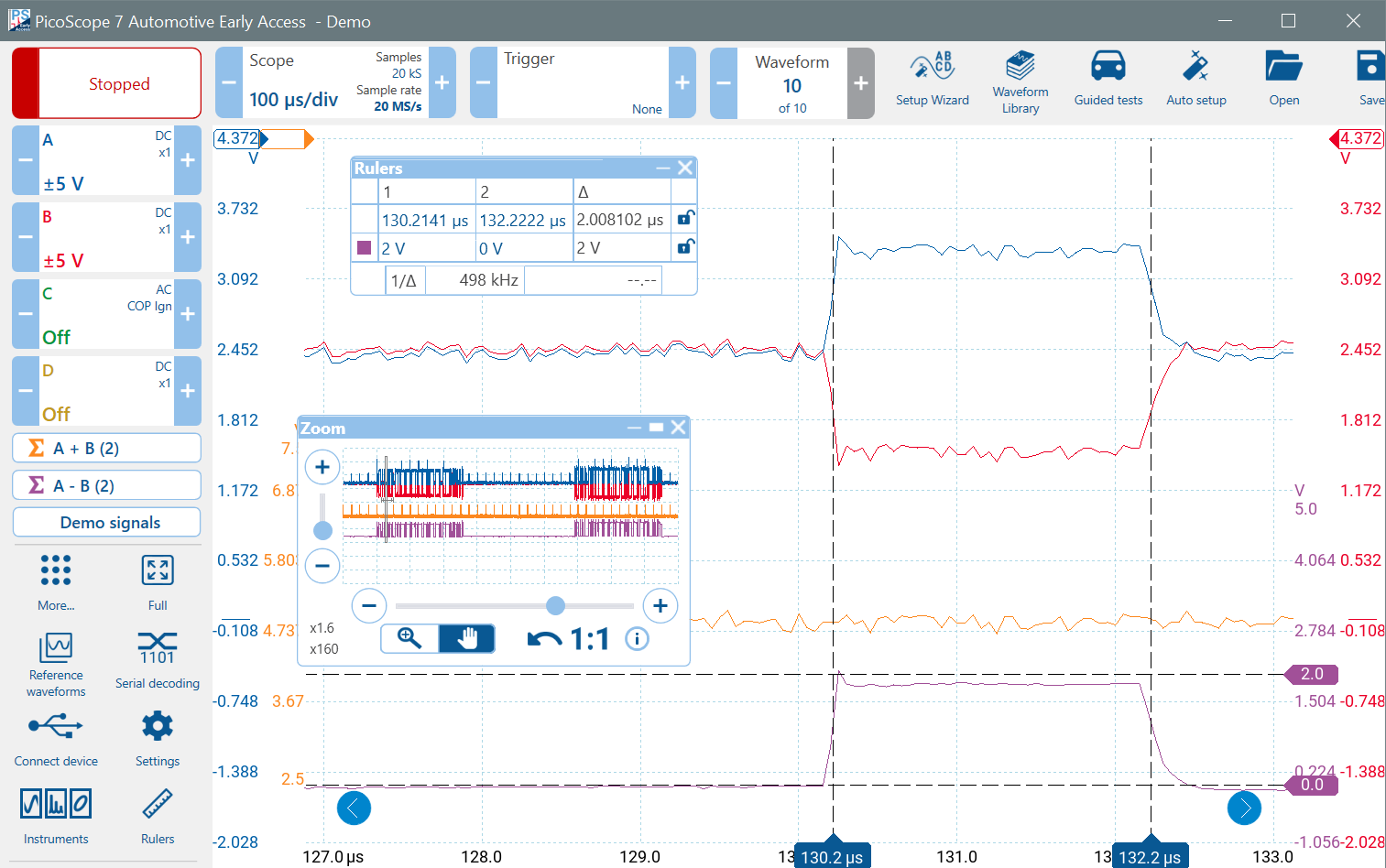
Zoom into a narrow bit near the beginning of the message (to avoid finding a fast CAN-FD bit, if applicable) and use the time rulers to measure its width. Set the rulers at a point about halfway up the edge. In the image below, I measured 498 kHz, which is approximately 500 kb/s.
Analysing the Zoomed Waveforms
Remember that the difference signal is inverted. When the difference signal is at 2 V, then a dominant bit (0) is being received. When it is at 0 V, then a recessive bit (1) is being received.
Also, notice that the rise-time of the difference signal (recessive to dominant transition) is faster than the fall time. The CAN bus reacts faster when actively driven than when it returns to the passive (recessive) state.
Now that you have zoomed into the signal, notice the reduction in noise and increase in the signal quality of the difference signal. Also, notice the overshoot caused by the use of test leads. The overshoot is not bad here, but can be far worse, depending on the system being tested. Also, remember the effect on the CAN bus itself might be different from the scope end of a test lead, which is what you are seeing, three or five metres away from the actual CAN bus. This is why using a proper 10:1 probe is so important.
The real ringing and overshoot levels might be far worse than those displayed. The demo scope only samples at 20 MS/s and cannot resolve the true extent of the problem. When you use a real PicoScope, you will be able to see problems like that much more clearly.
Next we will use the data rate that we have just determined to decode the CAN data messages.
Also, visit our CAN Bus Videos Page.